


Chapter 5: Advanced Serverboard Setup
5-15
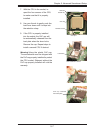
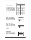
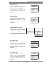
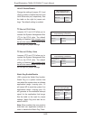
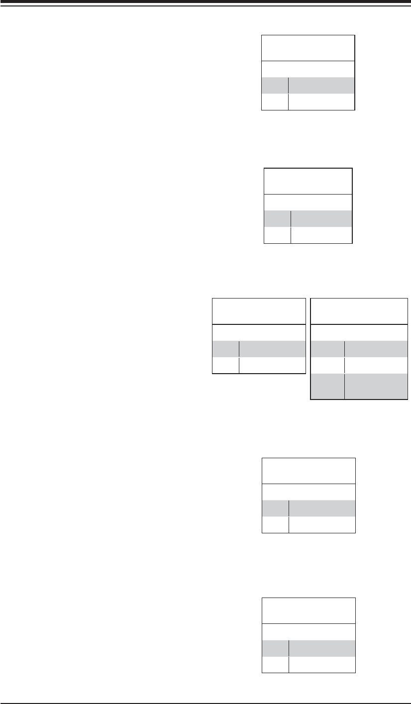
Reset Connector
The reset connector is located on pins
3 and 4 of JF1 and attaches to the
reset switch on the computer chas-
sis. See the table on the right for pin
defi nitions.
Reset Button
Pin Defi nitions (JF1)
Pin# Defi nition
3 Reset
4 Ground
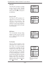
Overheat/Fan Fail LED (OH)
Connect an LED to the OH connection
on pins 7 and 8 of JF1 to provide ad-
vanced warning of chassis overheat-
ing. Refer to the table on the right for
pin defi nitions.
OH/Fan Fail LED
Pin Defi nitions (JF1)
Pin# Defi nition
7 Vcc
8 Ground
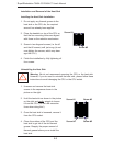
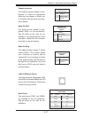
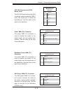
NIC2 LED
Pin Defi nitions (JF1)
Pin# Defi nition
9 Vcc
10 Ground
NIC2 (LAN2) LED
The LED connections for LAN2 are
on pins 9 and 10 of JF1. Attach an
LED cable to display network activ-
ity. See the table on the right for pin
defi nitions.
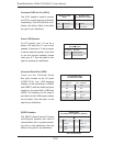
NIC1 LED
Pin Defi nitions (JF1)
Pin# Defi nition
11 Vcc
12 Ground
NIC1 (LAN1) LED
The LED connections for LAN1 are
on pins 11 and 12 of JF1. Attach an
LED cable to display network activ-
ity. See the table on the right for pin
defi nitions.
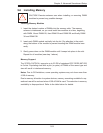
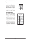
OH/Fan Fail Indicator
Status
State Defi nition
Off Normal
On Overheat
Flash-
ing
Fan Fail
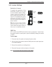
Power Fail LED
The Power Fail LED connection is
located on pins 5 and 6 of JF1. Re-
fer to the table on the right for pin
defi nitions.
PWR Fail LED
Pin Defi nitions (JF1)
Pin# Defi nition
5 Vcc
6 Ground