


Chapter 5: Advanced Serverboard Setup
5-3
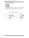
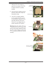
Connecting Data Cables
The cables used to transfer data from the peripheral devices have been carefully
routed to prevent them from blocking the fl ow of cooling air that moves through
the system from front to back. If you need to disconnect any of these cables, you
should take care to keep them routed as they were originally after reconnecting
them (make sure the red wires connect to the pin 1 locations). The following data
cables (with their locations noted) should be connected. (See the layout on page
5-12 for connector locations.)
Control Panel cable (JF1)
Floppy drive cable (Floppy)
7045A-3
SAS drive data cables (SAS0 ~ SAS7)
7045A-T
SATA drive data cables (I-SATA0 ~ I-SATA5)
SGPIO cable (T-SGPIO-1, T-SGPIO-2)
Important! Make sure the the cables do not come into contact with the fans.
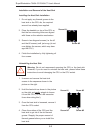
Connecting Power Cables
The X7DCA-3/X7DCA-i has a 24-pin primary power supply connector (JPW3) for
connection to the ATX power supply. In addition, there is a 4-pin secondary power
connector (JPW1) as well as an 8-pin processor power connector (JPW2) that
must be connected to your power supply. See Section 5-9 for power connector
pin defi nitions.
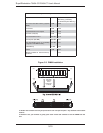
Connecting the Control Panel
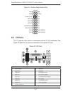
JF1 contains header pins for various front control panel connectors. See Figure 5-1
for the pin locations of the various front control panel buttons and LED indicators.
All JF1 wires have been bundled into a single cable to simplify this connection. Make
sure the red wire plugs into pin 1 as marked on the board. The other end connects
to the Control Panel PCB board, located just behind the system status LEDs on
the chassis. See Chapter 5 for details and pin descriptions.
•
•
•
•
•