


3–Pump 33-Station Controllers Chapter 4: Operation 30 of 51
Reviewing Pump Status
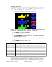
The “Pump Status” screen is the counterpart of the “Station Status” screen. To reach the
“Pump Status” screen from any other screen, touch Menu on the right-hand side of the
screen, and then touch Pumps. The “Pump Status” screen appears.
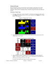
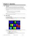
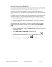
Figure 12: “Pump Status” Screen During Operation
The status of each pump is color-coded. You can see an explanation of each status by using
the online help. To do so from this screen, complete the following steps:
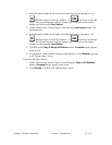
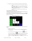
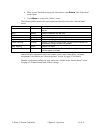
1. Touch Menu. The “Menu” screen appears.
2. Touch Help. The “Help Menu” screen appears.
3. Touch Pump States. The “Pump Symbols Help” screen appears, explaining the
status represented by each color.
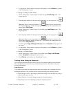
4. When you are finished reviewing the information, touch Return. The “Help Menu”
appears.
5. Touch Menu to return to the “Menu” screen.
The following table explains the status represented by each color at the Station Status screen.
Color Label Description
Gray outline Offline Pump is not enabled. The controller ignores any alarms.
Yellow Ready Pump is off, waiting for demand from a station.
Blue Idle Pump is on, waiting for demand from a station. If there is no
demand before the end of the auto shutdown delay, the pump
will turn off.
Green Loading Pump is conveying material to a station.
Blue, blinking Blow Back Pump’s air filter is being cleaned by blowing compressed air
backward through it.
Red, blinking Alarm Pump is in alarm.
Red outline, blinking Critical Pump is in critical alarm. The controller has disabled the pump
until the alarm is cleared.
Additional basic information about each pump, including configuration settings and the
number of hours the pump has been running, is available at the “Pump Setup” screen. For
details on configuration settings, see page 44. For details on the hour meter, see page 36.