


©
National Instruments Corporation 9 SSR Series Modules and Backplanes
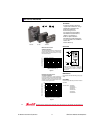
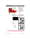
output modules the LED is on when the module is turned on. See the
Manufacturer Data Sheets section for further information.
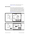
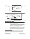
Signal Connections
Connect external devices to the SSR modules using the screw terminals.
Two screw terminals are dedicated to each module. Screw terminal
pair 1 and 2 are for module 0, terminal pair 3 and 4 are for module 1, and
so on. In the case of the DC modules, the odd numbered screw terminal is
always the positive terminal and the even numbered screw terminal is the
negative terminal. On the load side, a 5 A fuse protects each module. This
fuse is always located on the even numbered or negative screw terminal to
the module. Figures 8 through 11 show typical signal connections. See the
Manufacturer Data Sheets section for further information.
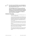
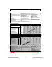
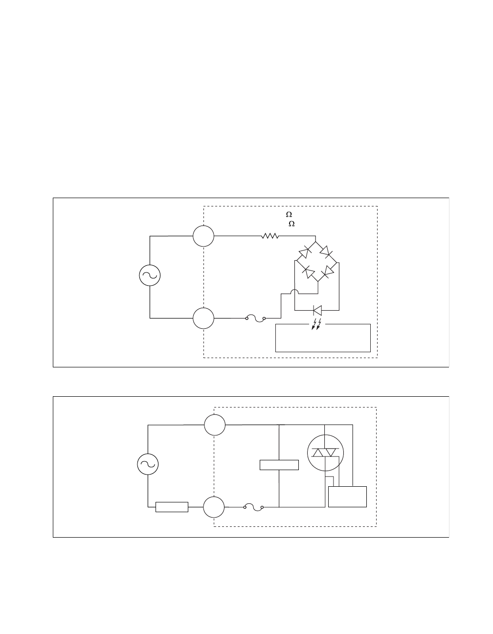
Figure 8.
IAC5 and IAC5A Signal Connections
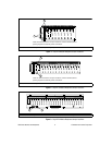
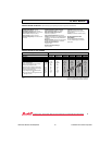
Figure 9.
OAC5 and OAC5A Signal Connections
5 A
IAC 5 (22 k )
IAC 5A (60 k )
IAC 5
90 to 140 VAC
IAC 5A
180 to 280 VAC
Even Backplane
Terminal
Odd Backplane
Terminal
User Signal
Source
AC
Input
Module
Digital Signal Conversion
to DAQ Device
5 A
0AC 5
24 to 140 VAC
0AC 5A
24 to 280 VAC
Even Backplane
Terminal
Odd Backplane
Terminal
User Power
Source
Load
Snubber
Trigger
Circuit
AC
Output
Module