©
National Instruments Corporation 3 SSR Series Modules and Backplanes
The dropout voltage and current specifications for the output modules are
given in the Manufacturer Data Sheets section. For most control
applications, such as controlling motors or lamps, these requirements are
not difficult to meet.
A second difference between these output modules and conventional relays
is that they do not turn off completely. A small leakage current flows all the
time even in the off state. For most control applications, this current causes
no problems.
Output SSR modules require a certain amount of current from the digital
control for the module to turn on. If the DAQ device sends a logic high
signal, the output module turns off and no current flows. If the DAQ device
sends a logic low signal, the output module turns on and current flows from
the +DC control or V
cc
to the -DC control. This current must be large
enough to turn on the output module. If the DAQ device or digital control
cannot sink enough current through the -DC control, the module does not
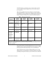
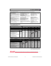
turn on. Refer to Table 1 to find the minimum logic control current required
to turn on each output module.
Note Make sure you pair the output module with a DAQ device that provides sufficient
control current. For example, the following National Instruments DAQ devices do
not work reliably with the SSR-OAC-5 and SSR-OAC-5A: the DIO-24 (6503),
DIO-96 (6508), Lab/1200 Series, AT-MIO-16D/AT-MIO-16DE extended DIO
lines, DAQCard-700, PC-LPM-16, and PC-AO-2DC.
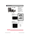
SSR Backplanes
This section describes the SSR backplane in detail including connection,
function, SSR module installation, and field connections.
Connection
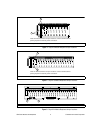
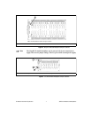
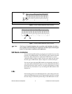
All four SSR backplanes function similarly, but they accommodate a
different number of modules. Each backplane has a special cabling scheme
to maximize the number of modules in use.
Table 1. Minimum Control Logic Current Required
Output Module Control Current
ODC5 5 mA
OAC5 12 mA
OAC5A 12 mA


