


SSR Series Modules and Backplanes 14
©
National Instruments Corporation
561 Hillgrove Avenue • LaGrange, Illinois 60525 • USA • Phone: (708) 354-1040 • Fax: (708) 354-2820 • http://www.grayhill.com
An ISO-9001 Company
SPECIFICATIONS Specifications apply over operating temperature range unless noted otherwise.
Output Specifications
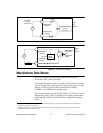
Load Current Range: 0.02 to 3.5 Amps for part
numbers beginning 70 and 70G; 0.02 to 3.0
Amps for 70M modules; 0.02 to 1.0 Amp for
70-ODC5A, 70M-ODC5A and 70G-ODC5A.
Maximum current is limited by data noted in
Figure 1.
Power Dissipation:1.0 Watt/Amp typical; 1.5
Watt/Amp typ. for 70-ODC5A, 70M-ODC5A
and 70G-ODC5A.
Surge Current: 5 Amps maximum for 1 second
On State Voltage Drop: 1.2 Volts maximum;
1.75 Volts maximum for 70-ODC5A, 70M-
ODC5A and 70G-ODC5A.
Clamping Voltage: 80 Vdc maximum; 360
Vdc maximum for 70-ODC5A, 70M-ODC5A
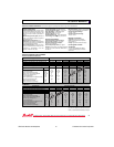
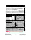
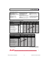
Miniature, Normally Open 70M-ODC5 70M-ODC5A 70M-ODC5B 70M-ODC15 70M-ODC15B 70M-ODC24 70M-ODC24B
Standard, Normally Open 70-ODC5 70-ODC5A 70-ODC5B 70-ODC15 70-ODC15B 70-ODC24 70-ODC24B
Specifications Units
Maximum Line Voltage Vdc 60 200 60 60 60 60 60
Load Voltage Range Vdc 3-60 4-200 3-60 3-60 3-60 3-60 3-60
Max. Off-state Leakage @ 60 Vdc mA 1.5 .010 .010 1.5 .010 1.5 .010
Maximum Turn-on Time µSe c 20 75 75 20 75 20 75
Maximum Turn-off Time µSec 50 750 500 50 500 50 500
Nominal Logic Voltage (Vcc) Vdc 5 5 5 15 15 24 24
Logic Voltage Range Vdc 2.5-10 2.5-9 2.5-10 10-18 10-18 15-30 15-30
Max. Logic Supply Current mA 14 18 14 9 9 9 9
@ Nominal Vcc
Nominal Input Resistance (Rx) Ω 300 220 300 1800 1800 2700 2700
Minimum Drop Out Voltage Vdc 1 1 1 1 1 1 1
Maximum Reverse Logic Voltage Vdc -5 -5 -5 -5 -5 -5 -5
Type/Function Grayhill Part Number
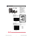
Standard and Miniature Modules
SPECIFICATIONS BY PART NUMBER–Solid State Modules
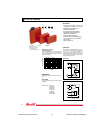
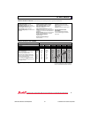
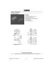
G5 Modules
Type/Function
G5 Fusible, Normally Open
Specifications Units
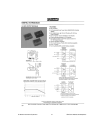
SPECIFICATIONS BY PART NUMBER–Dry Contact Modules 70-ODC5R, 70M-ODC5R and 70G-ODC5R
Output Specifications
Load Voltage: 100 Vdc/120 Vac maximum
Contact Rating: 10 Watts maximum
Switching Current: 0.5 A dc maximum. Induc-
tive loads require diode suppression.
Carry Current: 1.0 A maximum. Inductive loads
require diode suppression.
Life Expectancy:
At 10 Vdc: 10 mA-200,000,000 operations min.
At 48 Vdc: 100 mA-500,000 operations min.
At 120 Vac: 80 mA-500,000 operations min.
Contact Resistance: 250 mΩ maximum
Turn-on Time: 1.0 mSec maximum (including
bounce)
Turn-off Time: 1.0 mSec maximum (including
bounce)
Off-State Leakage Current: 2 µA maximum at
60 Hz
Input Specifications
Nominal Logic Voltage: 5 Vdc
Logic Voltage Range: 4.8-6.0 Vdc
Max Logic Supply Current at Nominal
Voltage: 10 mA
Input Resistance: 500 Ω
Pick Up Voltage: 0.8 Vdc minimum
Drop Out Voltage: 2.5 Vdc minimum
Reverse Logic Voltage: 5 Vdc maximum
and 70G-ODC5A.
Thermal Resistance(R
θJA
): 20˚C/Watt typical
Transient Power Dissipation: 400 Watts at
1 mS non-recurring
General Characteristics
Insulation Resistance (Input to Output;
Input or Output to Case): ≥ 10
10
Ohms
Dielectric Strength Input to Output:
Solid State: 4000 Vac (rms) minimum
Dry Contact: 1500 Vac (rms) minimum
Input to Output Capacitance: 10 pF typical
Vibration: 20 G?s peak or .06" double amplitude
10–2000 Hz per MIL–STD–202, Method 204, Con-
dition D
Mechanical Shock: 1500 G?s 0.5 mS half-sine
per MIL–STD–202, Method 213, Condition F
Storage Temperature Range:
-40˚C to +125˚C
Operating Temperature Range:
Solid State: -40˚C to +100˚C
Dry Contact: -20˚C to +85˚C
Materials and Finishes
Terminals: Copper wire, tin plated
Case: Solvent resistant thermoplastic; meets
UL94V–0
Potting: High thermal conductive epoxy
UL Recognition & CSA Certification
UL file number E58632 and CSA file number
LR38763 apply to all modules shown here.
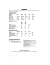
70G-ODC5 70G-ODC5A 70G-ODC5B 70G-ODC15 70G-ODC15B 70G-ODC24 70G-ODC24B
Maximum Line Voltage Vdc 60 200 60 60 60 60 60
Load Voltage Range Vdc 3-60 4-200 3-60 3-60 3-60 3-60 3-60
Max. Off-state Leakage @ 60 Vdc mA 1.5 .010 0.01 1.5 0.01 1.5 0.01
Maximum Turn-on Time µSe c 20 75 75 20 75 20 75
Maximum Turn-off Time µSec 50 750 500 50 500 50 500
Nominal Logic Voltage (Vcc) Vdc 5 5 5 15 15 24 24
Logic Voltage Range Vdc 4-6 4-6 4-6 10-20 10-20 18-32 18-32
Max. Logic Supply Current mA 13 13 13 9 9 9 9
@ Nominal Vcc
Nominal Input Resistance (Rx) Ω 150 150 150 1500 1500 2700 2700
Minimum Drop Out Voltage Vdc 1 1 1 1 1 1 1
Maximum Reverse Logic Voltage Vdc -5 -5 -5 -5 -5 -5 -5
Grayhill Part Number
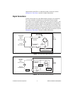
DC OUTPUT MODULES
35