


©
National Instruments Corporation 15 SSR Series Modules and Backplanes
561 Hillgrove Avenue • LaGrange, Illinois 60525 • USA • Phone: (708) 354-1040 • Fax: (708) 354-2820 • http://www.grayhill.com
An ISO-9001 Company
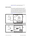
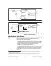
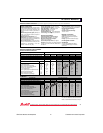
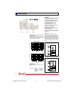
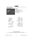
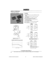
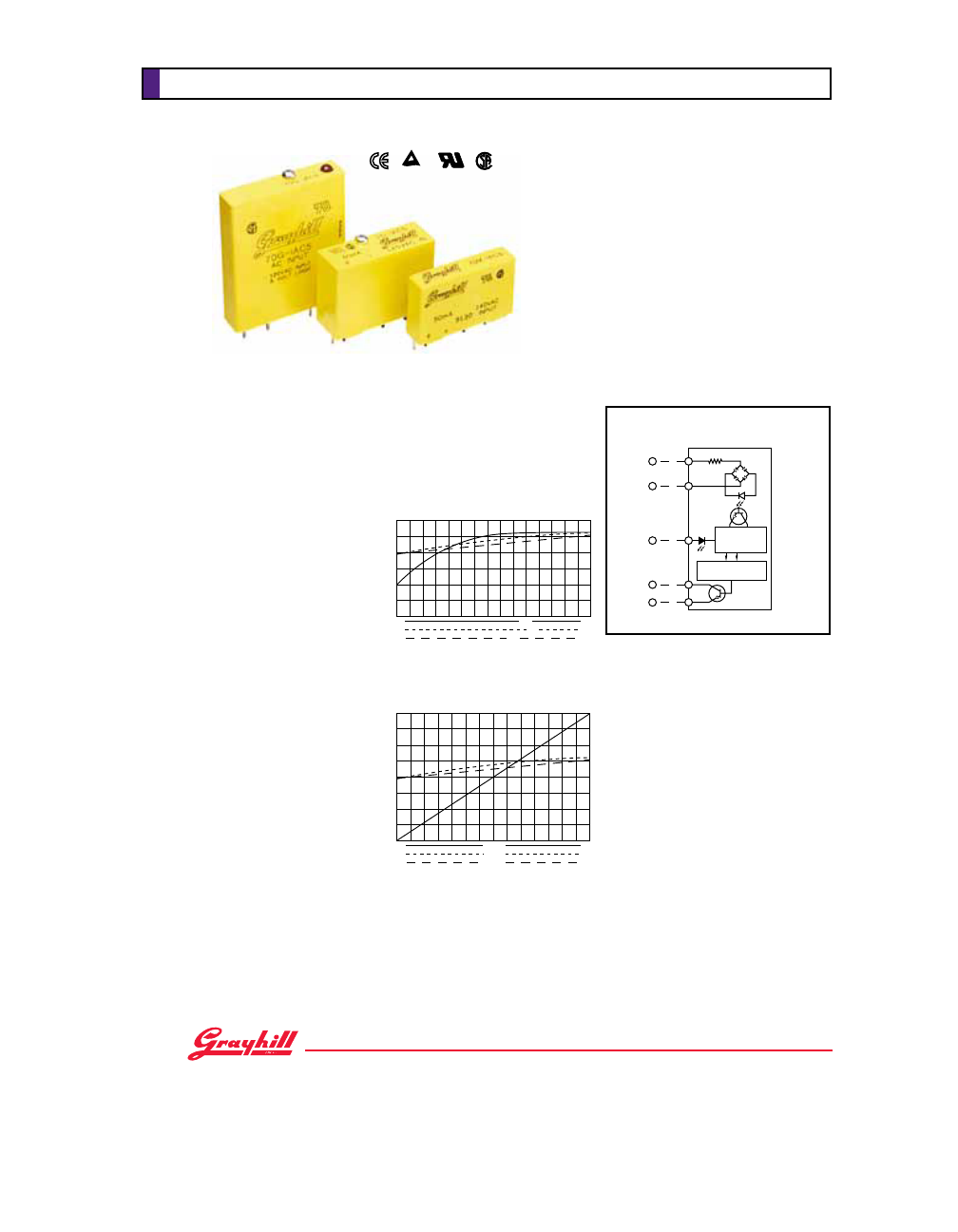
CIRCUITRY
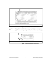
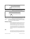
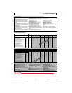
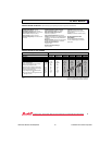
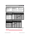
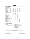
Typical Logic Supply Current Versus Logic
Supply Voltage
For Figures 1 and 2, all values were measured at
25˚C. The logic supply voltage continuum
represents the voltage range for each of the three
nominal voltages (5, 15, and 24 Vdc).
Status LED in G5 module only.
Negative True Logic
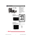
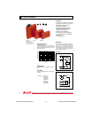
FEATURES
• Transient Protection: Meets the
requirements of IEEE 472, “Surge
Withstanding Capability Test”
• G5 Modules Passed IEC801.2,
IEC801.3, and IEC801.4
• UL Recognized, CSA Certified
• 4000 Vac Optical Isolation
• G5 Module has Built-in Status LED
• Lifetime Warranty
LOGIC SUPPLY VOLTAGE (VDC)
Figure 1
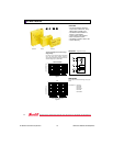
Standard and Mini
G5
70G-IAC 70-IAC 70M-IAC
LOGIC CURRENT (mA)
TUV Rheinland
••
* *
10
8
6
4
3
8
15
5
15
24
6
18
30
1
2
3
4
5
Rx
VAC
+VCC
OUTPUT
GROUND
INPUT
VOLTAGE
HYST. CIRC.
CURRENT
REGULATING
10
8
6
4
4.5
10
17
5.25
14.0
23
6
18
30
12
LOGIC SUPPLY VOLTAGE (VDC)
Figure 2
LOGIC CURRENT (mA)
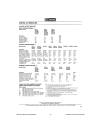
AC INPUT MODULE
38
DIMENSIONS
For complete dimensional drawings, see pages
29-30.
*Part Numbers: 70G-IAC5
70G-IAC5A
70G-IAC15
70G-IAC15A
70G-IAC24
70G-IAC24A