


©
National Instruments Corporation 11 SSR Series Modules and Backplanes
561 Hillgrove Avenue • LaGrange, Illinois 60525 • USA • Phone: (708) 354-1040 • Fax: (708) 354-2820 • http://www.grayhill.com
An ISO-9001 Company
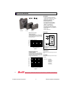
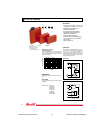
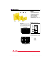
AC OUTPUT MODULES
FEATURES
• Transient Protection: Meets the
requirements of IEEE 472, “Surge
Withstanding Capability Test”
• SPST, Normally Open
• Zero Crossing Turn-On
• UL Recognized, CSA Certified
• G5 Modules Passed IEC801.2,
IEC801.3, and IEC801.4
• 4000 Vac Optical Isolation
• G5 Modules Provide Replaceable
5 x 20 mm Glass Fuse and Built-in
Status LED
• Lifetime Warranty
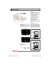
G5 FUSES
Fuses are 5 Amp Littlefuse part number 217005 or
equivalent.
*Part Numbers: 70G-OAC5
70G-OAC5A
70G-OAC5A-11
70G-OAC15
70G-OAC15A
70G-OAC24
70G-OAC24A
TUV Rheinland
••
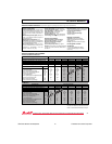
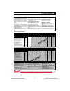
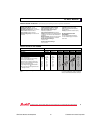
AMBIENT TEMPERATURE (˚C)
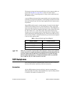
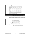
Maximum Current Versus
Ambient Temperature
The chart indicates continuous current to limit the
junction temperatures to 100˚C. Information is
based on steady state heat transfer in a 2 cubic
foot sealed enclosure.
Figure 1
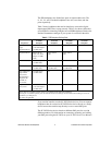
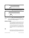
NUMBER OF FULL CYCLES AT 60 HERTZ
Figure 2
Maximum Peak Surge Current
Versus Surge Duration
Information is based on a supply frequency of
60 Hz sinusoidal and a resistive or inductive load.
Application of maximum surge current may not be
repeated until the module temperature has re-
turned to its steady state value.
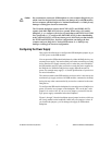
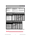
DIMENSIONS
For complete dimensional drawings, see pages
29-30.
STANDARD & G5 PACKAGE
MINIATURE PACKAGE
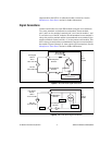
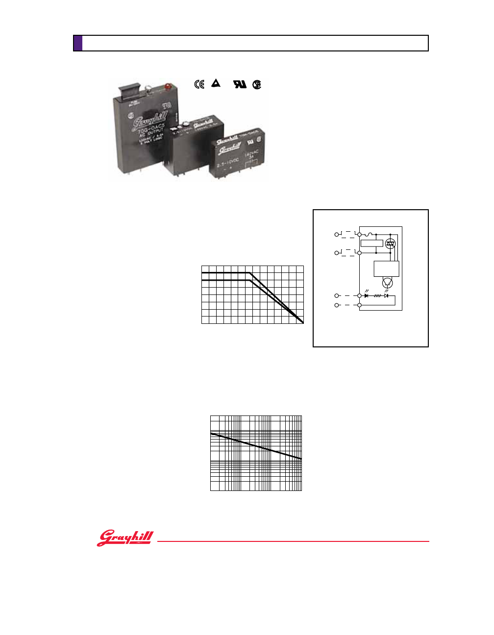
Fuse and Status LED in G5 modules only.
Trigger circuit provides zero voltage turn-
on except for part numbers 70-OAC5A5
and 70-OAC5A-11, which have random
(fast) turn-on.
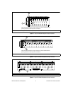
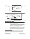
CIRCUITRY
70G-OAC 70-OAC 70M-OAC
LOAD CURRENT (AMPS)
PEAK SURGE CURRENT (AMPERES)
* *
4
3
2
1
- 40 - 20 0 20 40 60 80 100
80
40
60
30
20
10
6
4
3
1
1
12346 2010 40 60100
1000
300
200
100
1
2
3
4
Rx
VAC
DC CONTROL
TRIGGER
CIRCUIT
SNUBBER
LOAD
LOAD
–
+
32