


SSR Series Modules and Backplanes 12
©
National Instruments Corporation
561 Hillgrove Avenue • LaGrange, Illinois 60525 • USA • Phone: (708) 354-1040 • Fax: (708) 354-2820 • http://www.grayhill.com
An ISO-9001 Company
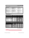
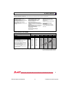
AC OUTPUT MODULES
SPECIFICATIONS–All Modules Specifications apply over operating temperature range unless noted otherwise.
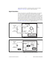
Output Specifications
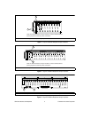
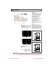
Load Current Range (rms): 0.03 to 3.5 Amps
for part numbers beginning 70 and 70G. 0.03 to
3.0 Amps for part numbers beginning 70M.
Maximum current is limited by data noted in
Figure 1.
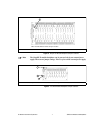
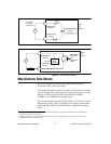
Maximum Surge Current (peak): 80 Amps at
60 Hz, 1 cycle; 25 Amps at 60Hz, 60 cycles as
qualified by Figure 2.
Maximum Zero Voltage Offset: 8 V
peak
Static dV/dT: 3000 volts per microsecond typi-
cal, measured under open circuit conditions; not
to exceed peak blocking voltage.
Turn-on Time (60 Hz): 8.3 mSec maximum
(except 70-OAC5A5 which is 200 µSec and
70-OAC5A-11, 70M-OAC5A-11 and 70G-
OAC5A-11 which are 100 µSec)
Turn-off Time (60 Hz): 8.3 mSec maximum
On State Voltage Drop (peak): 1.5 volts max.
Power Dissipation: 1.0 Watt/Amp typical
Load Power Factor: 0.4 minimum
Frequency Range: 25 to 70 Hz
Thermal Resistance (R
θθ
θθ
θJA
): 25˚ C/Watt typical
I
2
t for Fusing (t = 8.3 mS): 35 A
2
per Sec min.
General Characteristics
Insulation Resistance (Input to Output;
Input or Output to Case): ≥ 10
10
Ohms
Dielectric Strength Input to Output:
4000 Vac (rms) minimum
Input to Output Capacitance: 6 pF typical
Vibration: 20 G?s peak or .06” double amplitude
10–2000 Hz per MIL–STD–202, Method 204,
Condition D
Mechanical Shock: 1500 G?s 0.5 mS half-sine
per MIL–STD–202, Method 213, Condition F
Storage Temperature Range:
-40˚C to +125˚C
Operating Temperature Range:
-40˚C to +100˚C
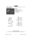
Materials and Finishes
Terminals: Copper wire, tin plated
Case: Solvent resistant thermoplastic;
meets UL94V–0
Potting: High thermal conductive epoxy
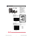
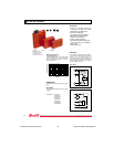
UL Recognition and CSA
Certification
UL file number E58632 and CSA file
number LR38763 apply to all modules
shown here.
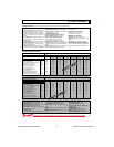
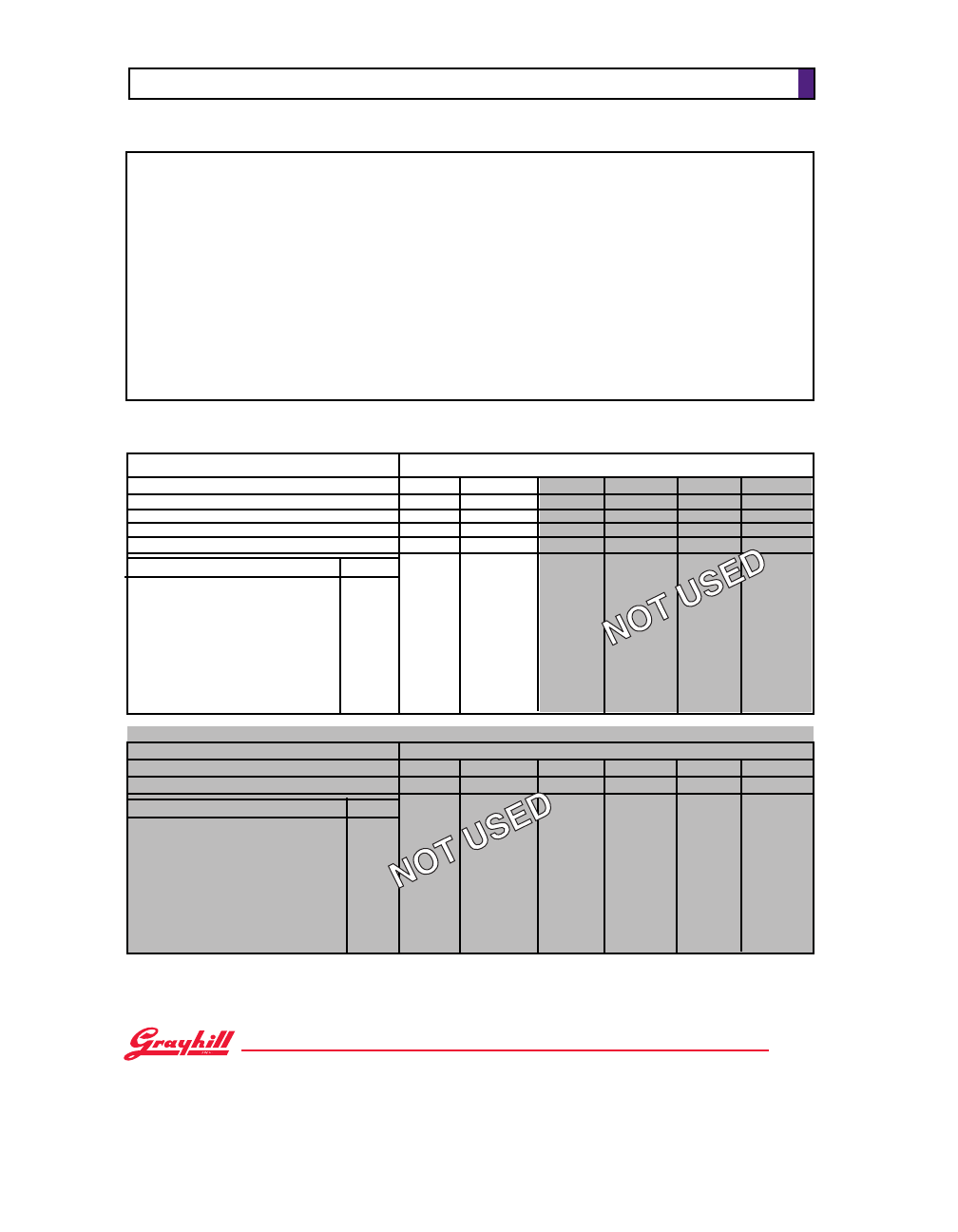
Miniature, Normally Open, Random Turn-on 70M-OAC5A-11
Miniature, Normally Open, Zero Voltage Turn-on 70M-OAC5 70M-OAC5A 70M-OAC15 70M-OAC15A 70M-OAC24 70M-OAC24A
Standard, Normally Closed, Random Turn-on 70-OAC5A5
Standard, Normally Open, Random Turn-on 70-OAC5A-11 70-OAC24A-11
Standard, Normally Open, Zero Voltage Turn-on 70-OAC5 70-OAC5A 70-OAC15 70-OAC15A 70-OAC24 70-OAC24A
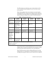
Specifications Units
Nominal Line Voltage Vac 120 240 120 240 120 240
Load Voltage Range Vac 24-140 24-280 24-140 24-280 24-140 24-280
Minimum Peak Blocking Voltage Volts 400 600 400 600 400 600
Maximum Off-state Leakage @ 60Hz. mA, rms 2 4 2 4 2 4
Nominal Logic Voltage (Vcc) Vdc 5 5 15 15 24 24
Logic Voltage Range Vdc 2.5-10 2.5-10 10-18 10-18 15-30 15-30
Max. Logic Supply Current @ Nominal Vcc mA 16 16 9 9 9 9
Nominal Input Resistance (Rx) Ω 240 240 1800 1800 2700 2700
Minimum Drop Out Voltage Vdc 1 1 1 1 1 1
Maximum Reverse Logic Voltage Vdc -5 -5 -5 -5 -5 -5
Type/Function Grayhill Part Number
Standard and Miniature Modules
SPECIFICATIONS BY PART NUMBER
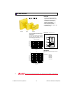
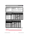
G5 Modules
Grayhill Part Number
Type/Function
G5 Fusible, Normally Open, Zero Voltage Turn-on
G5 Fusible, Normally Open, Random Turn-on
Specifications Units
70G-OAC5 70G-OAC5A 70G-OAC15 70G-OAC15A 70G-OAC24 70G-OAC24A
70G-OAC5A-11
Nominal Line Voltage Vac 120 240 120 240 120 240
Load Voltage Range Vac 24-140 24-280 24-140 24-280 24-140 24-280
Minimum Peak Blocking Voltage Volts 400 600 400 600 400 600
Maximum Off-state Leakage @ 60Hz. mA, rms 2 4 2 4 2 4
Nominal Logic Voltage (Vcc) Vdc 5 5 15 15 24 24
Logic Voltage Range Vdc 4-6 4-6 8-20 8-20 18-32 18-32
Max. Logic Supply Current @ Nominal Vcc mA 20 20 12 12 8 8
Nominal Input Resistance (Rx) Ω 100 100 1000 1000 2700 2700
Minimum Drop Out Voltage Vdc 1 1 1 1 1 1
Maximum Reverse Logic Voltage Vdc -5 -5 -5 -5 -5 -5
Available from your local Grayhill Distributors
For prices and discounts, contact a local Sales
Office, an authorized local Distributor, or Grayhill.
33