


18
FVR-C9S-2UX
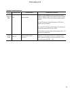
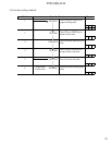
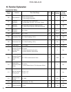
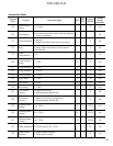
Terminal Function Explanation
Classi-
fication
Terminal Code Terminal Name Explanation of Function
Main
Circuit
L1, L2, L3
Commercial power supply input
terminals
For connection of 3-Phase 200 to 230V commercial power
supply
U, V, W
Drive Output Terminals For connection of a 3-Phase motor
E (G) Drive Grounding Terminals
Grounding terminal of drive chassis (case). Be sure to ground
the drive to prevent electric shock or to lower noise
Frequency
Setting
13
Power Supply for Frequency
Setting
Used as a power supply for frequency setter (variable
resistor: 1 - 5K ohm) (DC + 10V, 10mA max)
12 Frequency Setting Voltage Input DC 0 - +10V / 0 - 100% (Input resistance: 22K ohm)
11*
Frequency Setting Common
Terminal
Common terminal for frequency setting signals 12 and 13
Control
Input
FWD
Forward/Stop Command Input
Terminal
Forward-direction operation takes place when FWD-CM is
closed. Drive decelerates and stops when FWD-CM is
opened
REV
Reverse/Stop Command Input
Terminal
Reverse-direction operation takes place when REV-CM is
closed. Drive decelerates and stops when REV-CM is opened
BX
Motor Coast-to-Stop Input
Terminal
•Drive output is cut off instantly and motor will coast-to-
stop when BX-CM is closed. Alarm signal is not outputted.
•This functions as multistep frequency selection terminal X2
when changing function.
THR External Alarm Input Terminal
•When THR-CM is opened during operation, drive output is
cut (motor will coast-to-stop) and an alarm signal is
outputted. This signal is latched and reset by RST input.
•This functions as multistep frequency selection terminal X1
when changing functions.
RST Alarm Reset Terminal When RST-CM is closed, the drive fault is reset.
CM* Control Input Common Terminal Common terminal for control input signals
C92-03
* Electric potential of 11 terminal is identical with that of CM terminal.
10. Terminal Function Explanation