


6050-065-L-11-08
23
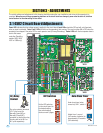
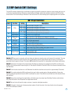
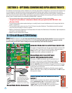
3.2 DIP-Switch SW 1 Settings
The two DIP-switches located on the circuit board are used to program the operator to operate in various modes and to turn on
or off various operating features. Whenever a switch setting is changed, power to the operator must be turned OFF and then
turned back on for the new setting to take affect. Check and review ALL switch settings prior to applying power to the operator.
Switches 1-2 These work in conjunction with each other and determine when the relay on the board will be activated. This relay
can be used as a switch for various functions such as illuminating a warning light when the gate is moving, or turning on a
green light when the gate is full open. This relay is NOT available for these uses if it is being used for the shadow loop function.
Switch 3 Determines if the output of the loop detector (DoorKing loop detectors only) plugged into the EXIT port will be sent
directly to the microprocessor to open the gate, or if the output is directed to Terminal 4 where it can then be connected to other
input terminals.
Switch 4 Turns the auto close timer on or off. Maximum time that the close timer can be set for is approximately 23 seconds.
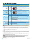
Switch 5 This switch enables the 4502 circuit board to be used in either a swing gate or slide gate application. Some older
DoorKing slide gate operators did use the 4501 circuit board for control. This switch is here to allow use of this board on these
older products.
Switch 6 Sets up the circuit board for single button or 3-button (open-close-stop) logic (DoorKing 3-button control stations
only). Keep this switch in the ON position for single button control.
Switch 7 Sets up the circuit board for single or primary / secondary (dual) gate operation.
Switch 8 If the gate is forced open, the tamper-protect system will start the motor in the close direction when the operator
senses the forced open condition.
Switch Function Setting Description
SW 1 (Top 8 Switches)
Open loop
Logic Output
OFF
ON
OFF
ON
OFF
ON
OFF
ON
1-OFF
1-OFF
1-ON
1-ON
2-OFF
2-ON
2-OFF
2-ON
Auto-Close
Timer
Slide Gate
Swing Gate
Dual Operators
Single Operator
Relay
3
4
5
7
1 and 2
Terminal 12 is the output from the open detector.
Terminal 12 is an open input.
Auto-close timer is OFF. Manual input required to close gate.
Auto-close timer is ON. Adjustable from 1-23 seconds to close gate.
OFF for Slide gate operator.
ON for Swing gate operator.
OFF
ON
3-Button
Single Button
6
OFF when using a 3-button station.
ON when using a single button control.
Switch must be OFF when bi-parting (dual) gates are used.
Switch must be ON for single operator.
OFF
ON
Tamper Protect
8
Tamper protect is OFF.
Tamper protect is ON.
Relay activates when gate is open.
Relay activates when gate is not closed.
Relay activates when gate is opening and open.
Relay activates when gate is opening and closing.