


6050-065-L-11-08
15
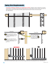
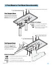
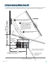
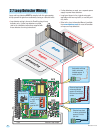
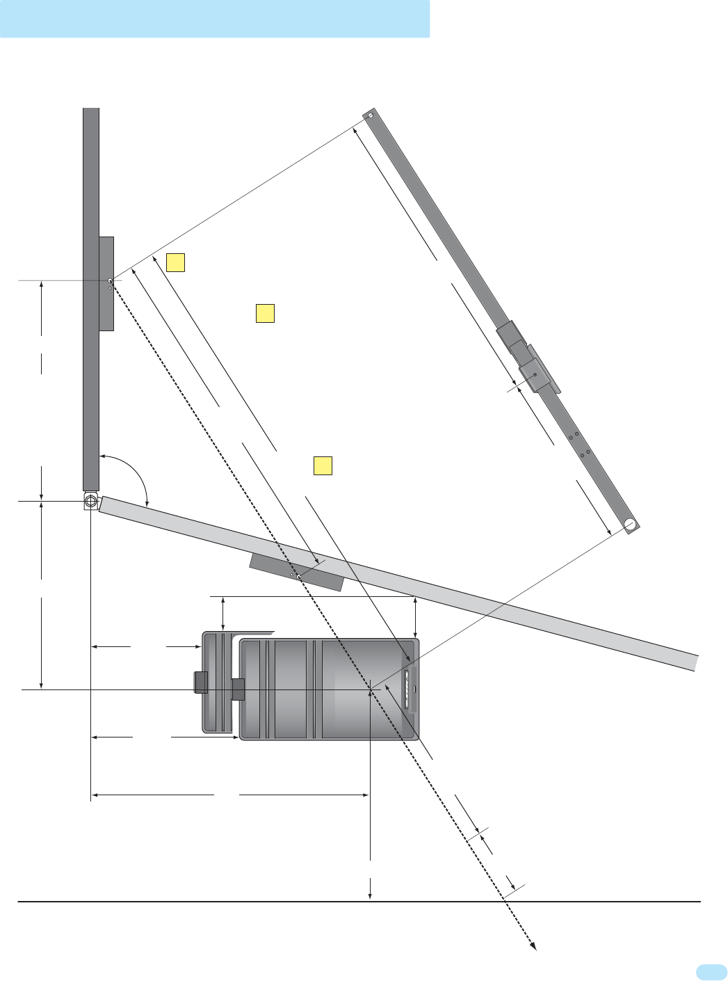
1.9 Gates Opening Wider Than 90°
O
pen Gate
Connecting Arm
Elbow
Ass
embly
Crank Arm
Closed Gate
19.25”
14.5”
44.5”
40”
22.25”
22.25”
8.5”
62.25”
36”
24”
27”
28”
Operator
Output Shaft
An imaginary line drawn from the
closed gate bracket through the
open gate bracket MUST intersect
the operator output shaft. The
crank and connecting arm’s pivot
point calculations will be made
from the 2 measurements taken
from this line.
Note: Mount operator square to the fence line
and NOT parallel to the open gate.
The installation of an operator opening gates wider that 90° is the same for 1.3 through 1.8 except the operator and concrete
pad will be in a different position. Individual requirements can be calculated following this 105° demonstrated sample.
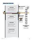
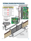
105°
Sample
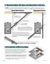
5”
4”
Crank arm’s pivot point measurement
in the open position on imaginary line.
Safety cover’s installed
measurement for any
configuration.
Connecting arm’s pivot point measurement
62.25” minus (crank arm) 22.25” = 40”
Crank arm’s pivot point measurement
44.5” divided by 2 = 22.25”
Gate bracket
should not be
mounted any
farther than
28” for any
configuration.
Distance needed for arm
clearance in the open position.
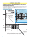
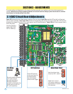
Arm Assembly
1
2
3
Imaginary Line
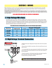
Convenience Open
6100 Cover
(See 6100 detail
on page 10)
Standard Operator
Cover