


Deploying FCoE (FIP Snooping) on Dell PowerConnect 10G Switches: M8024-k, 8024, and 8024F
4
Cisco Nexus 5548UP CLI example .............................................................................. 52
Appendix B - Network Switch Versions ........................................................................... 56
References ............................................................................................................ 56
About Dell ............................................................................................................ 56
Figures
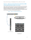
Figure 1. Dell PowerConnect™ M8024-k Switch (10G Ethernet) .............................................. 6
Figure 2. Dell PowerConnect™ 8024F (10G Ethernet) ......................................................... 6
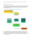
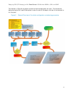
Figure 3. General overview of deployment ...................................................................... 8
Figure 4. Disabling simple mode .................................................................................. 9
Figure 5. Simple 1-link connection between devices ......................................................... 10
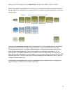
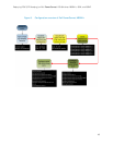
Figure 6. General Overview of the whole configuration and planning procedure ........................ 11
Figure 7. Overview of parallel configuration ................................................................... 12
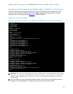
Figure 8. Example commands for Dell PowerConnect M8024-k (can be copied and pasted) ........... 13
Figure 9. Configuration overview of Dell PowerConnect M8024-k .......................................... 16
Figure 10. Sample CLI for Cisco Nexus 5020 (can be copied and pasted) ................................... 17
Figure 11. Sample CLI for Cisco Nexus 5548 (can be copied and pasted) ................................... 18
Figure 12. Cisco Nexus 5000 series configuration sequence ................................................... 20
Figure 13. M1000e Chassis Management Controller -> Server Overview -> Properties -> WWN/MAC
information for Blade Server 3’s “B” fabric CNA port 2 (B2). ............................................ 21
Figure 14. Example of show interface brief command ......................................................... 22
Figure 15. show spanning-tree summary command showing current configuration with ports states .. 23
Figure 16. show flogi database command showing devices that have completed fabric login .......... 23
Figure 17. Example of show zoneset active command ......................................................... 23
Figure 18. Show interface status results ......................................................................... 24
Figure 19. show spanning-tree blockedports command ........................................................ 25
Figure 20. Show fip-snooping command which gives a brief status on available ENode’s, and FCF’s .. 25
Figure 21. show lldp dcbx interface all ........................................................................... 26
Figure 22. Show lldp dcbx interface te1/0/20 detail .......................................................... 27
Figure 23. Multiple port link (LAG) configuration between switches and storage ......................... 30
Figure 24. Multiple port link (LAG) Cisco 5020 configuration (can be copied and pasted) ............... 31
Figure 25. Multiple port uplink (LAG) M8024-k configuration (can be copied and pasted) ............... 33
Figure 26. Multiple link configuration between switches and storage ....................................... 35
Figure 27. Multiple port link Cisco 5020 configuration (can be copied and pasted) ....................... 36
Figure 28. CoS settings to establish minimum bandwidth for FCoE queue .................................. 37
Figure 29. Fabric separation as preferred method for management of networks and storage .......... 38