


Deploying FCoE (FIP Snooping) on Dell PowerConnect 10G Switches: M8024-k, 8024, and 8024F
37
Step by Step explanation of CLI example for the Cisco Nexus 5000 Series using NPV (only
covering the differences from the single port configuration)
o feature NPV– enables the NPV feature which turns off zoning. The FC side of the Nexus 5000 series
switch effectively turns into just a FC gateway (just passing FC out to another switch). When this
feature is enabled the Cisco Nexus 5000 series switch will have to do a full reload because it is
completely changing the way it deals with the FC packet behavior. Be prepared for this reload
because it may impact a currently running network environment.
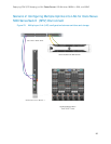
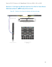
Configuring the Dell PowerConnect M8024-k,8024,and 8024F for FIP Snooping
with Cisco Nexus 5000 series switch in NPV mode.
The configuration will be the same as previously mentioned in the single or multiple port
configurations. The simplicity of the PowerConnect 8024 series switch setup for FIP Snooping is one of
the great advantages to using this in an FCoE network.
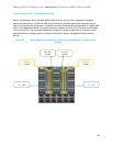
ETS Behavior and CoS configurations on the PowerConnect 8024 series switches
The 8024 family devices will pass ETS information between end devices and the FCF but local settings
are not changed in the 8024 series switches. This process allows for a best effort approach in the
default configuration. This will be sufficient for the typical business usage model but for more in-depth
settings the following CoS settings can be set in order to apply exact minimum thresholds for the
queues that will be used for FCoE or iSCSI. These minimum thresholds are a guaranteed minimum
bandwidth for the queues involved, in this case priority queue 3 for FCoE or 4 for iSCSI. The following
example is applicable to the FCoE class of service queue 3 settings. (These settings can also be found in
the appendix in the full CLI example
.)
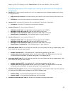
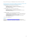
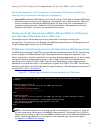
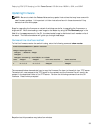
CoS settings to establish minimum bandwidth for FCoE queue Figure 28.
NOTE: In the above example the first setting is made on interfaces te1/0/1 through 16. These are
all the internal server-facing ports on the M8024-k modular switch. The settings for te1/0/20 are
based on this port being an uplink from the M8024-k modular switch to the Cisco Nexus 5000 series
switch. As mentioned above the full configuration with these settings in place can be seen in
the Appendix A – M8024-k CLI example
.
! Default priority is 0 (CoS queue 0). Untagged frames receive the default priority
treatment.
!
interface range te1/0/1-16
! Set CoS queue 3 to strict priority (not WRED) per 802.1Qaz
cos-queue strict 3
! Reserve 50% bw for CoS queue 3
cos-queue min-bandwidth 0 0 0 50 0 0 0
exit
interface te1/0/20
! Set CoS queue 3 to strict priority (not WRED) per 802.1Qaz (traffic selection class 0)
cos-queue strict 3
! Reserve 50% bw for CoS queue 3 - other queues are best effort.
! This bandwidth is shared with other queues if not used
cos-queue min-bandwidth 0 0 0 50 0 0 0
Exit