


Deploying FCoE (FIP Snooping) on Dell PowerConnect 10G Switches: M8024-k, 8024, and 8024F
15
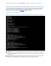
o interface te1/0/20 – this moves into the interface te1/0/20 configuration
switchport general pvid 20 – establishes the native VLAN as 20, you must remove VLAN
1 in order for this to function correctly
switchport general allowed vlan add 20 - adds VLAN 20 the trunk as an untagged VLAN
switchport general allowed vlan add 1000 tagged - – this sets up a trunk with a
tagged VLAN of 1000 (the FCoE VLAN), and includes the native VLAN as untagged if
general mode is enabled.
switchport general allowed remove vlan 1 – this removes vlan 1 which would typically
be the native vlan otherwise.
switchport mode general – this enables the port for mode general
spanning-tree cost 0 – sets spanning tree cost to 0
spanning-tree port-priority 0 – sets this ports priority to 0 so that it has the lowest
spanning tree priority in case a loop is created elsewhere on the switch
lldp dcbx port-role auto-up – sets the DCBx port-role to be auto-up which dynamically
sets the configuration-source for an FCF connection
fip-snooping port-mode fcf – enables the port for fip-snooping from an FCF connection
exit - exits the interface configuration
exit – exits from configuration mode
Critical steps: The “copy running-configuration startup-configuration” command should be issued
after important steps so that the switch will retain the configuration settings when the switch is
next rebooted or if a power loss occurs. It is also a good practice to copy a well-validated working
configuration to a separate location such as the management station for the networks, and have a
backup-configuration saved local to the switch.
Further explanation of key points:
• The spanning-tree settings in this example are established to keep the port from being
potentially blocked by spanning-tree. This could occur because another cable is plugged into a
port with a lower priority, causing a loop. When the uplink port is set to 0 it will have the
lowest priority and therefore most likely not end up in a blocked state.
• A second key setting to note is “switchport general allowed vlan remove 1”. This command
must be entered if you are choosing to use a different PVID or native VLAN. A port cannot have
two native VLANs. In this example the configuration is set to use VLAN 20 since typically the
recommendation is to have regular untagged traffic on a different VLAN other than just 1 for
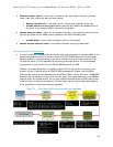
segregation of the network. In addition when the FCF sends information to the fip-snooping
bridge (FSB) or M8024-k in this case, the M8024-k is receiving the initial information for
negotiation on its untagged vlan (vlan 20 in this case). Once the initial negotiations have
occurred properly the FCoE traffic will traverse the FCoE VLAN (in this case VLAN 1000).
• The last configuration line “fip-snooping port-mode fcf” is also key to this configuration. This
line establishes where the FCF is attached to the switch. With this setting the port is
configured to make Fibre Channel aware of the connection via this port to the forwarder. The
previous line “lldp dcbx port-role auto-up“, is setting this port to be aware of DCBx TLV’s, he
difference being the fip-snooping configuration line points to the port for using fip-snooping
tohe FCF, and the lldp configuration points to the point for doing DCBx negotiations.