


Deploying FCoE (FIP Snooping) on Dell PowerConnect 10G Switches: M8024-k, 8024, and 8024F
20
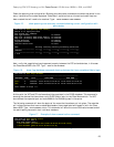
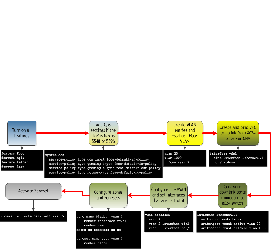
o Zone name blade1 vsan 2 – this will set the name for your zone (blade1 can be any chosen
name); vsan 2 will match the vsan you have created.
Member interface fc2/1 - this adds the fc2/1 interface as a member of the zone.
member pwwn xx:xx:xx:xx:xx:xx:xx:xx – adds the port WWN of the ENode device to
the zone. (insert the port WWN of the device being used).
o zoneset name set1 vsan 2 – move into the zoneset interface (in this case the name is set1 but
could be any name and the VSAN number is based on the FCoE VLAN being used.
member blade1 – this includes the blade1 zone into this zoneset.
o zoneset activate name set1 vsan 2 – activates the zoneset containing these zones.
Further explanation of key points:
• In order for devices to communicate end-to-end they must participate in the same VSAN. In this
sample configuration the VFC is bound to either the FCoE FIP MAC Address of the Converged
Network Adapter in the blade server or an actual interface that would be a connection from
the modular switch (in this case M8024-K) connecting the blade servers. The recommended
configuration for this is to bind to the FCoE FIP MAC address of the CNA.
However, as an easy setup step it is possible to bind a VFC to the physical interface or port-
channel in order to determine which FCoE FIP MAC addresses will present from the CNA’s.
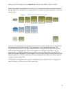
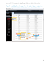
These can be noted and then matched with the M1000e’s CMC -> Server Overview -> WWN/MAC
Summary that can be seen in Figure 15 on the next page. This is applicable only to the M8024-k
modular switch with blade servers. For the rack-mounted 8024 switches the CNA’s would need
to be verified on the servers themselves. This verification can be done through each adapters
driver properties in the different operating systems.
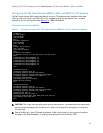
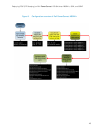
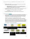
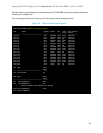
Cisco Nexus 5000 series configuration sequence Figure 12.