16 of 42 Doc 01-20099 Rev F
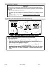
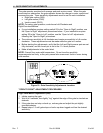
IMPORTANT: Before proceeding, see NOTES below.
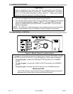
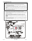
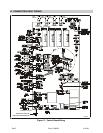
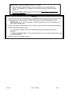
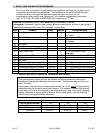
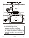
1. Wire all external control devices to their connections on the control board as
shown. See Appendix A for details on how each control input affects the gate
operator.
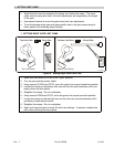
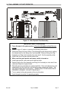
2. Connect the Master/Slave interconnect cable (see Master/Slave Systems for X3
Series Gate Operators, Part 1).
NOTES
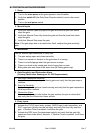
1. Disconnecting the STOP terminal from the COMMON terminal stops the gate and prevents all
commands from having any effect. Manual Open does not activate the Reclose Timer.
IMPORTANT: As per UL325 standards, install the Manual Input and Fire switches in the
line of sight with the gate.
2. If gate(s) are used for bi-directional traffic, the Exit Loop should be a directional loop detector.
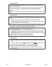
3. Inside and Outside Interrupt Loops:
♦ For maximum safety, Inside and Outside Interrupt loops require separate loop
detectors.
♦ Bi-part or Bi-part Latch: If only one loop detector is used, connect Outside loop to the
Inside loop detector.
4. Battery is used to store date and time.


