8 of 42 Doc 01-20099 Rev F
D. RUNNING INPUT WIRING
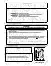
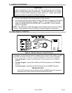
WARNING
Route but do not connect input wires at this time. If inputs are connected now, the
gate operator may activate at random during installation, potentially injuring installation
personnel.
1. Remove the plastic control box cover.
2. Run wires from input components conduits and Master/Slave conduits into control
box.
3. For Master/Slave wiring, refer to Master/Slave Systems for X3 Series Gate
Operators, Part 2.
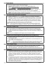
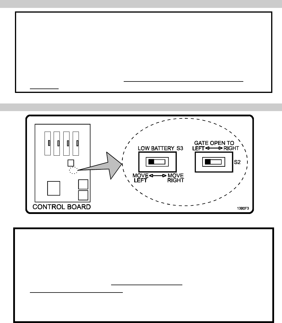
E. SETTING GATE OPEN DIRECTION SWITCHES S2 AND S3
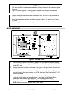
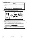
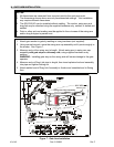
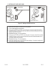
Figure 5. Gate Direction and UPS Low Battery Switch Locations.
NOTE: For swing gate operation, controls are Left/Clockwise and
Right/Counterclockwise.
• Switch S2 sets gate opening direction (open to left or open to right).
• Switch S2 is sensed only on power up, it should be set when the power is off, or
power should be cycled after setting the switch.
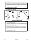
1. Set switch S2 to the Left for Clockwise Gate Opening, or to the Right for
Counterclockwise Gate Opening as required.
2. Set switch S3 to the direction you wish the gate to move (left or right) and remain
when the LOW BATTERY input is activated by an Uninterruptible Power Supply
(UPS).


