


4 of 42 Doc 01-20099 Rev F
NOTES
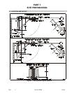
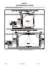
• Left Gate and Right Gate are determined by looking from inside the complex toward
the street.
• Figure 1 shows a typical Bi-Parting gate in standard and compact installations.
1. Always install gate operators inside of the fence line, NEVER on the public side of
the fence.
2. Mount all manual controls and activating devices at least 6 ft. away from the gate
for safety.
3. Allow enough clearance around the gate and the gate operator for installation and
service.
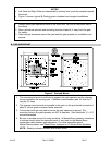
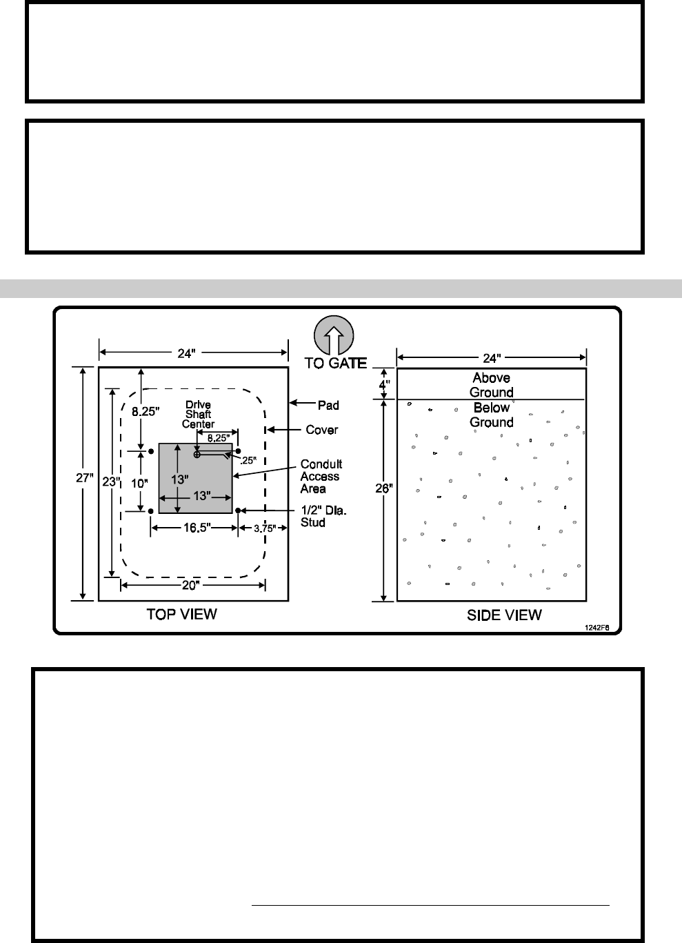
B. PAD AND MOUNT
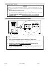
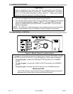
Figure 2. Pad and Mount.
1. The concrete pad must be sufficient to support the gate operator and the dynamic
forces created by the moving gate. LiftMaster recommends a pad 24” wide by 27”
long by 30” deep.
2. The operator must be level and parallel to the gate, so the pad should be level and
about 4” above grade to prevent water entrance.
3. Four anchor bolts are required to secure the gate operator to the pad. The
mounting holes in the gate operator are 5/8” in diameter. Red Head bolts ½” x 3½“
are recommended.
4. Be sure to provide access for wiring conduits. In Master/Slave systems, remember
to include conduit stubs for separate inputs (if any) and for the Master/Slave
connection cable between gate operators. For more information about
Master/Slave systems, see Master/Slave Systems for X3 Series Gate Operators.
NOTE: Shading indicates conduit stub access areas.