


07271B DCN6646 v
TABLE OF CONTENTS
MODEL T201 AMMONIA ANALYZER .............................................................I
CONSIGNES DE SÉCURITÉ ......................................................................... IV
1.0 T201 AMMONIA ANALYZER.................................................................7
1.1 Theory of Operation...................................................................................................... 10
1.1.1 Minimizing PMT Drift.......................................................................................... 11
1.1.2
Purging the Reaction Cell ..................................................................................... 11
1.2
Special Considerations For Ammonia Measurement ................................................... 12
1.3 Sample Filtration........................................................................................................... 12
1.4 T201 Analyzer Specifications....................................................................................... 13
2.0 CALIBRATION PROCEDURE .............................................................15
2.1 Zeroing the Analyzer .................................................................................................... 16
2.2 Spanning the Analyzer with Nitric Oxide Gas ............................................................. 17
2.3 Spanning the Analyzer with Ammonia Gas.................................................................. 19
3.0 CONFIGURABLE ANALOG OUTPUT OVERVIEW ...........................25
4.0 MAINTENANCE SCHEDULE...............................................................27
4.1 M501 NH
3
Maintenance ............................................................................................... 27
4.2 Replacing the Catalytic Cartridge................................................................................. 28
4.3 Replacing the Thermocouple........................................................................................ 29
4.4 AutoZero Flow Check................................................................................................... 31
5.0 ALARMS AND CAUTIONS ..................................................................33
5.1 Alarm ............................................................................................................................ 33
5.2 Caution.......................................................................................................................... 33
6.0 CALCULATING MOLY CONVERTER EFFICIENCIES ......................35
6.1 Purpose.......................................................................................................................... 35
6.2 Tools ............................................................................................................................. 35
6.3 Parts............................................................................................................................... 35
6.4 Procedure ...................................................................................................................... 35
7.0 T201 SPARE PARTS LIST...................................................................39
LIST OF FIGURES
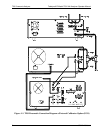
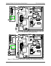
Figure 1-1. T201 Pneumatic Connection Diagram w/External Calibrator Option (ECO).. 8
Figure 1-2. T201 and M501 NH
3
Pneumatic Flow...........................................................9
Figure 1-3. T201 and M501 NH
3
with Zero and Span Valve Options Pneumatic Flow....9
Figure 3-1. Analog Output Connector............................................................................25
Figure 4-1. Catalytic Cartridge ...................................................................................... 28
Figure 4-2. Thermocouple Location...............................................................................29
LIST OF TABLES
Table 1-1. T201 Operating Specifications ..................................................................... 13
Table 2-1. Zero Calibration Procedure – Zero Gas through the SAMPLE Port ............. 16
Table 2-2. Zero Calibration Procedure - Zero
Gas through ZERO Port......................... 17
Table 2-3. NO Calibration Procedure – NO Gas through the SAMPLE Port
................. 18