


Teledyne API Model T201 NH
3
Analyzer Operator Manual Maintenance Schedule
07271B DCN6646 31
18. After the Auto-Tune process is completed, verify that the “process”
temperature is indicating that the desired temperature is stable and
being regulated.
The converter is now ready for operation.
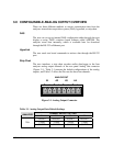
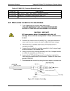
4.4 AUTOZERO FLOW CHECK
Since the T201 is an ammonia analyzer, the flow through the AutoZero
orifice is especially important. Check the AutoZero flow as follows:
1. This procedure should be performed with the sample pump running.
2. Remove the top cover of the analyzer. Locate the vacuum manifold at
the center rear of the chassis. Locate the 1/8” tube fitting located on
the very left side, as viewed from the rear of the analyzer. It will have a
label of “0.010” indicating the flow orifice installed.
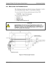
3. Remove the fitting and attach a calibrated flowmeter to the block fitting
capable of measuring in the range of 500 cc/min. The flowmeter
should indicate a flow of 500 cc/min 10%.
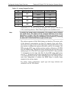
4. If the flow is outside this range (most likely lower, due to plugging):
1. Turn off the sample pump and instrument.
2. Remove the 1/8” pipe-to-tube fitting and remove the ¼” sintered filter
(p/n FL0000001). This filter is meant to protect the orifice; it will
usually become plugged and need replacement rather than the
orifice. Replace the filter, and then re-assemble the manifold.
Restart the sample pump and recheck the flow.
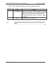
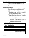
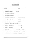
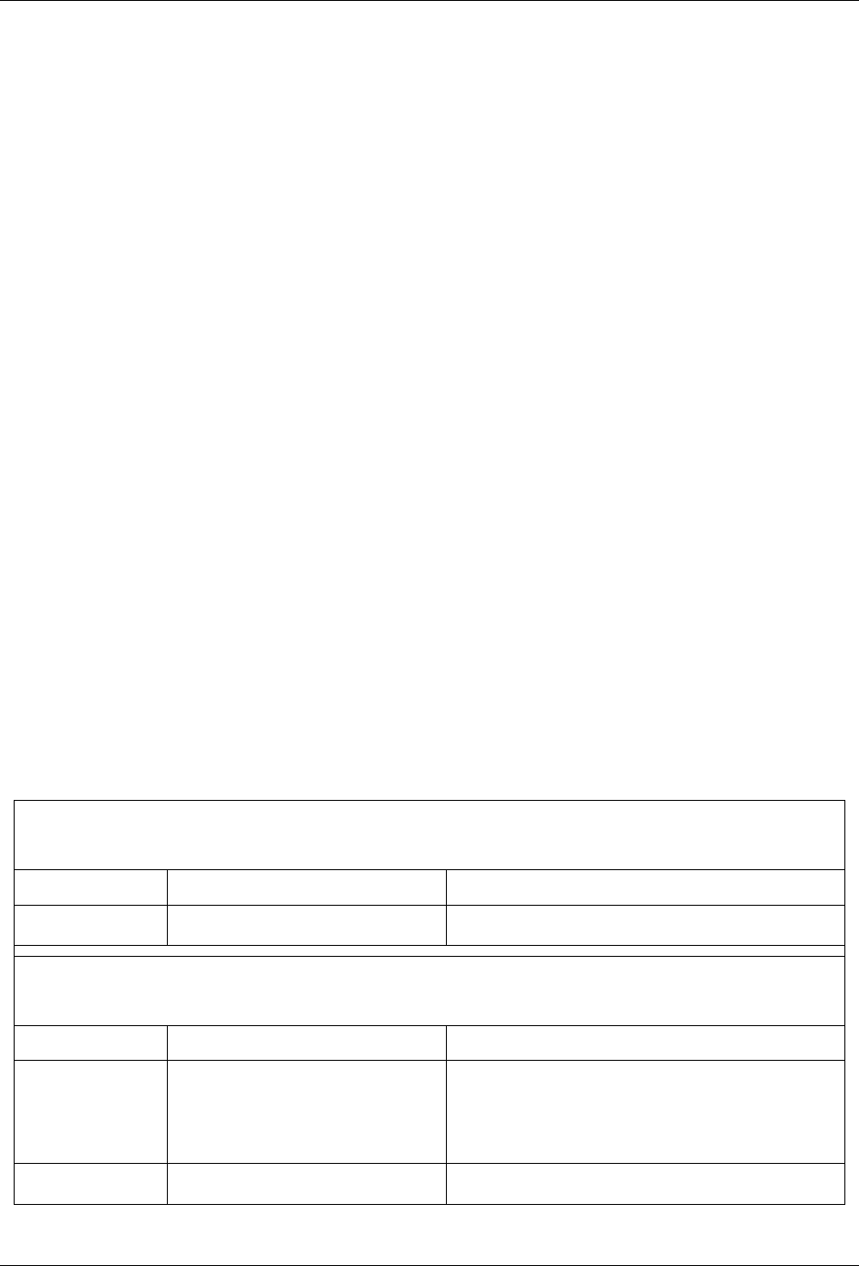
Table 4-3. Flow Check
M501
NH
3
CONVERTER SAMPLE FLOW CHECK
Note: Connect both the Teflon
tubes between analyzer and converter.
Gas Port Expected Flow (cc/min)
“SAMPLE IN” 1000 +/- 10 %
ANALYZER SAMPLE FLOW CHECK
Note: Disconnect both the Teflon
tubes between analyzer and converter.
Gas Port Expected Flow (cc/min)
“TO CONV”
1000 or 500, +/- 10 % When the analyzer is sampling TNx only, the
bypass flow is measured. Therefore, the flow
alternates between 500 and 1000 cc/min. This
is the NOx channel.
“FROM CONV” 500 +/- 10% This is the TNx channel.