


Configurable Analog Output Overview Teledyne API Model T201 NH
3
Analyzer Operator Manual
26 07271B DCN6646
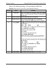
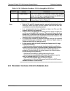
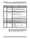
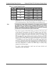
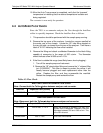
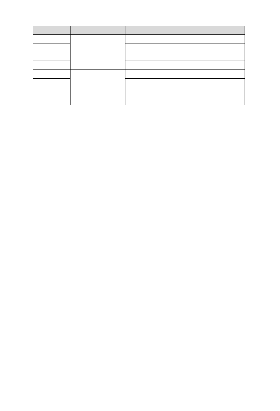
Table 3-2. Analog Output Pin-Outs
PIN ANALOG OUTPUT VOLTAGE SIGNAL CURRENT SIGNAL
1 V Out I Out +
2
A1
Ground I Out -
3 V Out I Out +
4
A2
Ground I Out -
5 V Out I Out +
6
A3
Ground I Out -
7 V Out N/A
8
A4
Ground N/A
Additionally A1, A2 and A3 may be equipped with optional 0-20 mA, or
4-20, current loop drivers. The 4-20 mA option is not available on A4.
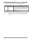
Note
In actuality the analog output configuration of the analyzer may be different
than stated above. The outputs can be configured differently at the factory
depending on whether they were assigned during the procurement of the
product. It is possible to check the configuration of the analyzer by accessing
the ANALOG I/O CONFIGURATION through the DIAG menu.
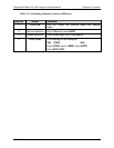
The analyzer operates in Dual Mode during gas detection. This means each
of the measured concentrations can have two separate slopes and offsets,
one for the low range and one for the high range. Though uncommon, a user
may decide to calibrate the analyzer with nitric oxide at, for example, 100
PPB using the LOW range and then perform another calibration at 450 PPB
using the HIGH range. Through the analog outputs the user can then assign
analog output A1 to TN
x
CNC1 and output A2 to TNxCNC2. Gases with the
“1” designation use the slope and offset for the LOW range, while gases
with the “2” designation will use the slope and offset for the HIGH range
.
It
is recommended that both the LOW and HIGH ranges be calibrated at the
same time. Independent of whether the HIGH range is actually being
outputted to the analog outputs.
For analog output configuration, signal type and range selection and
calibration, use the T200 manual.