


32 Intel NetStructure
®
MPRTM0020 Technical Product Specification – April 2006
RTM Management Architecture
• RTM Temp2
• RTM Temp3
• RTM Power Status
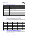
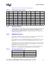
Table 15. Sensor Data Record for RTM
Sensor Name Description
Lower
Critical
Lower Non
Critical
Upper Non
Critical
Upper
Critical
RTM +1.8V For SAS Retimer 1.71 – – 1.89
RTM +3.3V For other Integrated Circuits 3.10 – – 3.47
RTM +3.3V SUS Early voltage for ADM1026 3.11 – – 3.46
RTM +5.0V For USB Interface 4.71 – – 5.23
RTM +5V SUS Early voltage for Hotswap LED 4.73 – – 5.25
RTM +12V Main voltage rail for other ICs/
peripherals
10.71 – – 13.10
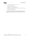
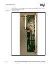
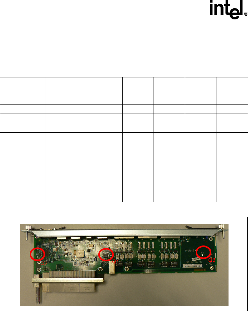
RTM Temp 1 Internal ADM1026 (U3)
[see Figure 16 for location]
-5 – 70 75
RTM Temp 2 External Thermal Diode (Q3)
[see Figure 16 for location]
-5 – 70 75
RTM Temp 3 External Thermal Diode (Q2)
[see Figure 16 for location]
-5 – 70 75
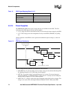
Figure 16. RTM Temperature Sensor Locations