


Intel NetStructure
®
MPRTM0020 Technical Product Specification – April 2006 3
Contents
1 Document Organization ................................................................................................................7
1.1 Acronyms and Terms............................................................................................................7
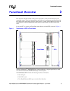
2 Functional Overview .....................................................................................................................9
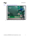
3 Operating the Unit .......................................................................................................................11
3.1 Introduction .........................................................................................................................11
3.2 RTM Installation Procedure ................................................................................................11
3.3 RTM Removal Procedure ...................................................................................................11
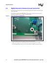
3.4 Digital Ground to Chassis Ground Connection...................................................................12
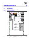
4 Module Components...................................................................................................................14
4.1 Block Diagram ....................................................................................................................14
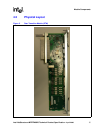
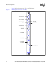
4.2 Physical Layout...................................................................................................................15
4.3 Components Description ....................................................................................................17
4.3.1 Serial Port Interface ...............................................................................................17
4.3.2 USB Interface ........................................................................................................18
4.3.3 Gigabit Ethernet Interface......................................................................................18
4.3.4 SAS Connector Interface.......................................................................................19
4.3.5 T1/E1 Connector Interface.....................................................................................20
4.3.6 Zone 3 Rear Transition Module Power Connector (P30).......................................21
4.3.7 Zone 3 Rear Transition Module Data/Control Connectors.....................................23
4.3.7.1 Zone 3 Rear Transition Module Data/Control Connector (P31).............23
4.3.7.2 Zone 3 Rear Transition Module Data Connector (P32) .........................24
4.3.7.3 Zone 3 Rear Transition Module Data Connector (P33) .........................24
4.3.8 Alignment Blocks ...................................................................................................25
4.3.9 ADM1026 Controller ..............................................................................................25
4.3.10 Power Supplies......................................................................................................26
4.3.11 SAS Redriver .........................................................................................................27
4.3.12 Board Status LEDs ................................................................................................27
4.3.13 RJ-45 Gigabit Ethernet Port LEDs.........................................................................28
5 RTM Management Architecture..................................................................................................30
5.1 Introduction .........................................................................................................................30
5.2 RTM FRU Control ...............................................................................................................30
5.3 M-state Machine .................................................................................................................30
5.4 Power Budget Management ...............................................................................................31
5.5 LED Management...............................................................................................................31
5.6 SDR Proxy ..........................................................................................................................31
5.7 RTM Sensor Proxy .............................................................................................................31
6 Detailed Specifications ...............................................................................................................33
6.1 Dimensions and Weight......................................................................................................33
6.2 Environmental Specification ...............................................................................................33
6.3 Mechanical Specifications ..................................................................................................33
6.3.1 Board Outline.........................................................................................................33
6.4 Reliability Specifications .....................................................................................................35