


28 Intel NetStructure
®
MPRTM0020 Technical Product Specification – April 2006
Module Components
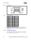
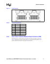
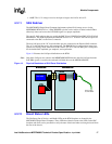
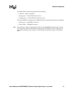
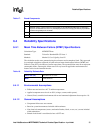
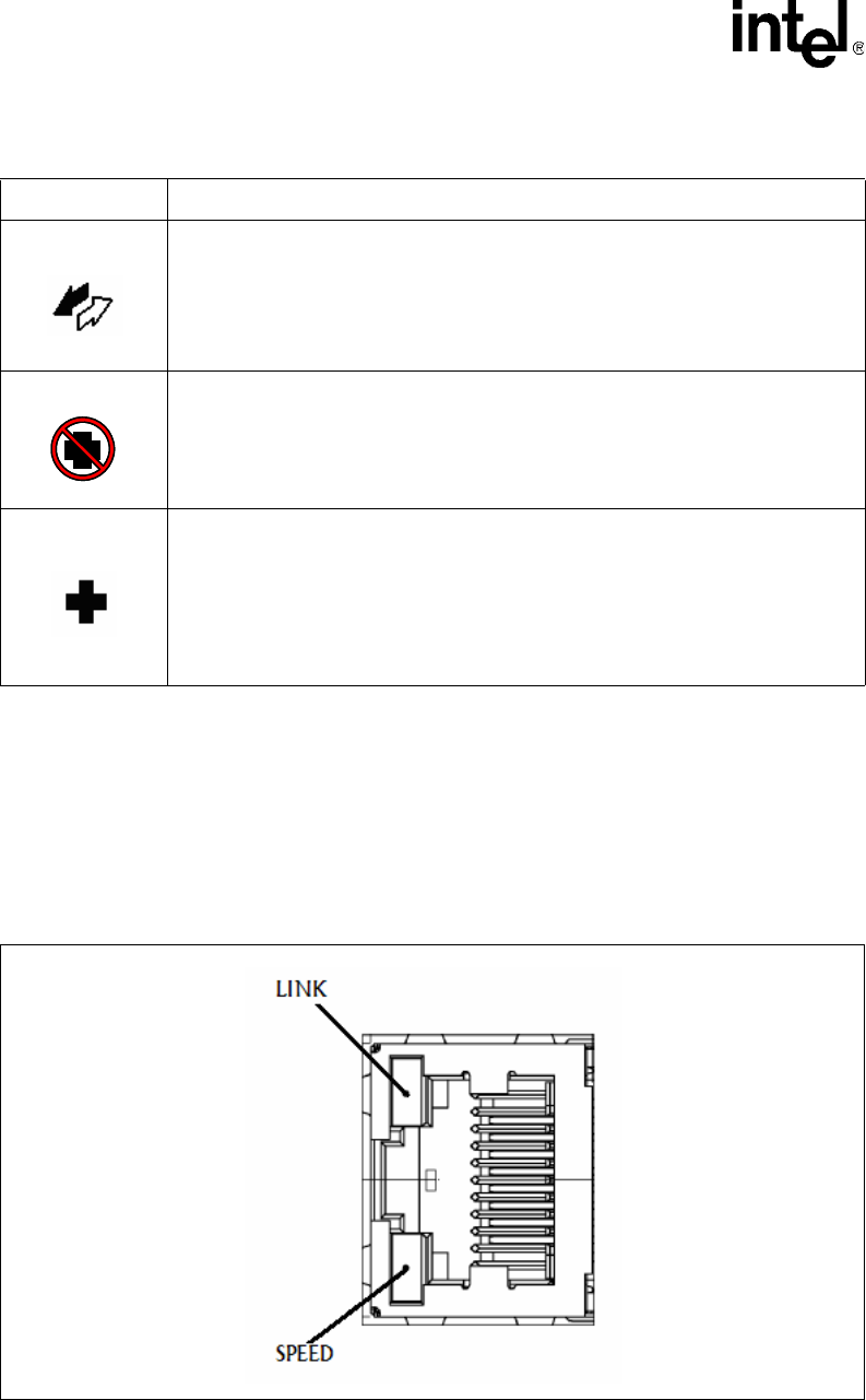
4.3.13 RJ-45 Gigabit Ethernet Port LEDs
The RJ-45 connector for each of the Gigabit Ethernet ports on the RTM has two indicator LEDs
integrated in the connector body.
As shown in Figure 15, the top LED represents the LINK LED while the bottom LED represents
the SPEED LED.
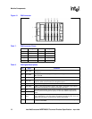
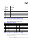
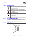
Table 14. Board Status LED Descriptions
LED Function
Hot Swap
Function: Hot Swap as defined in AdvancedTCA 3.0 Specification
It is also possible for a user to override the default behavior of the LED using
AdvancedTCA FRU LED Control commands.
Possible States: OFF / BLUE / SHORT BLINK / LONG BLINK
Blinking Blue: Preparing for removal/insertion. Long blink indicates activation is in
progress, short blink when deactivation is in progress
Out of Service
Function: Out of Service (AdvancedTCA LED 1).
RED: The board is out of service.
OFF: The board is running.
It is possible for a user to override the default IPMC behavior of the LED using
AdvancedTCA FRU LED Control commands.
Possible States: OFF / RED / AMBER
Health
Function: Health (AdvancedTCA LED 2). The SBC health is based on an aggregation of
IPMI sensors, like board temperature and voltage.
Green: The SBC is healthy.
Red: The SBC is not healthy.
It is possible for the user to override the default IPMC behavior of the LED using
AdvancedTCA FRU LED Control commands.
Possible States: OFF / GREEN / RED / AMBER
Figure 15. RJ-45 Ethernet Port LEDs