


24 Intel NetStructure
®
MPRTM0020 Technical Product Specification – April 2006
Module Components
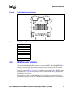
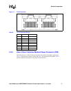
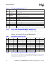
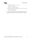
4.3.7.2 Zone 3 Rear Transition Module Data Connector (P32)
The P32 connector on the RTM connects to J32 on the MPCBL0020 Single Board Computer and is
used to route the T1/E1 signals from the PMC slots (on the SBC) to the RTM.
Table 11 provides the pinout of the P32 connector. AP1[x] designates T1/E1 signals that are routed
from PMC 1 while AP2[x] designates T1/E1 signals routed from PMC 2.
n
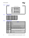
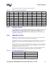
4.3.7.3 Zone 3 Rear Transition Module Data Connector (P33)
The P33 connector on the RTM connects to J33 on the MPCBL0020 Single Board Computer and is
used to route the remainder of the T1/E1 signals from PMC slot 3 on the SBC to the RTM. Table 12
provides the pinout of the P33 connector.
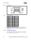
A6-F6
LNK[x], ACT[x],
SPD1000[x]
Represent the link, activity, and speed LEDs for the Fabric Interface Gigabit Ethernet that are
routed to the RTM
G6, F7 Reserved Reserved
G7, H7
PCIe_CLK+,
PCIe_CLK-
PCI Express reference clocks. Any SBC providing PCI Express (pins A3-H4) must provide
these signals.
* Not supported for the MPRTM0020 RTM.
A8-H9 Reserved Reserved
A10-
B10
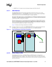
USB[0]+, USB[0]-
USB data signals. Note that the RTM’s 5 V power for the USB connections must be derived off
the 12 V rail.
C10 DSR# Data Set Ready signal for COM1 RS-232 connection.
D10 RXD# Received Data signal for COM1 RS-232 connection.
E10 RTS# Ready to Send signal for COM1 RS-232 connection.
F10 TXD# Transmit Data signal for COM1 RS-232 connection.
G10 CTS# Clear to Send signal for COM1 RS-232 connection.
H10 DTR# Data Terminal Ready signal for COM1 RS-232 connection.
Table 10. P31 Signal Descriptions (Sheet 2 of 2)
Pin Signal Comments
Table 11. RTM Connector (Zone 3) P32 Pinout
Pin A B C D E F G H
1 AP1[0]TX+ AP1[1]TX- AP1[0]RX+ AP1[0]RX- AP1[1]TX+ AP1[1]TX- AP1[1]RX+ AP1[1]RX-
2 AP1[2]TX+ AP1[2]TX- AP1[2]RX+ AP1[2]RX- AP1[3]TX+ AP1[3]TX- AP1[3]RX+ AP1[3]RX-
3 No Connect No Connect No Connect No Connect No Connect No Connect No Connect No Connect
4 No Connect No Connect No Connect No Connect No Connect No Connect No Connect No Connect
5 No Connect No Connect No Connect No Connect No Connect No Connect No Connect No Connect
6 AP2[0]TX+ AP2[1]TX- AP2[0]RX+ AP2[0]RX- AP2[1]TX+ AP2[1]TX- AP2[1]RX+ AP2[1]RX-
7 AP2[2]TX+ AP2[2]TX- AP2[2]RX+ AP2[2]RX- AP2[3]TX+ AP2[3]TX- AP2[3]RX+ AP2[3]RX-
8 No Connect No Connect No Connect No Connect No Connect No Connect No Connect No Connect
9 No Connect No Connect No Connect No Connect No Connect No Connect No Connect No Connect
10 No Connect No Connect No Connect No Connect No Connect No Connect No Connect No Connect