


22 Intel NetStructure
®
MPRTM0020 Technical Product Specification – April 2006
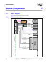
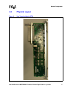
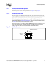
Module Components
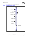
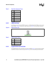
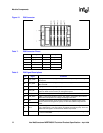
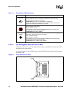
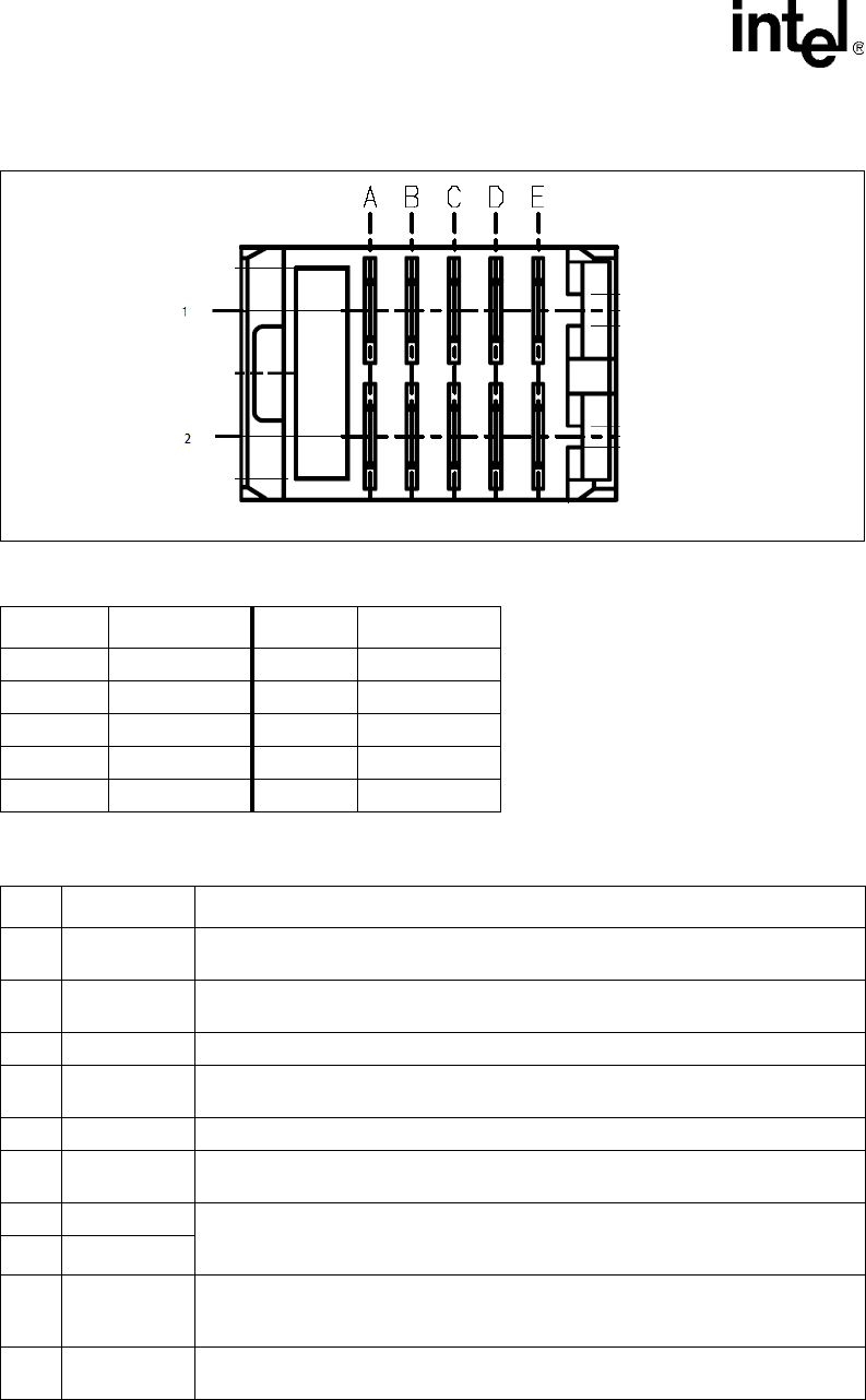
Figure 12. P30 Connector
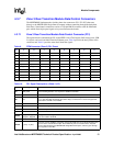
Table 7. P30 Connector Pinout
Pin Signal Pin Signal
A1 (L) Logic_GND A2 (L) Shelf_GND
B1 (L) Logic_GND B2 (L) +3.3V_MP
C1 (M) IPMI_Sclk C2 (M) IPMI_Sdata
D1 (S +12V D2 (S) +12V
E1 (S) PS1# E2 (S) ENABLE#
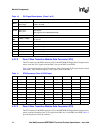
Table 8. P30 Signal Descriptions
Pin Signal Comments
A1 Logic_GND
Logic ground connection (long contact); provides return path for power and signal
connections.
A2 Shelf_GND
Shelf ground connection (long contact); provides safety ground contact between
SBC and RTM.
B1 Logic_GND Logic ground connection (long contact); see above.
B2 +3.3V_MP
Management power (long contact); provides up to 100mA to power management
system on RTM. Used exclusively for management power.
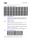
C1 IPMI_Sclk IPMB/I
2
C clock signal (medium contact)
C2 IPMI_Sdata
IPMB/ I
2
C data signal (medium contact); This signal is connected to the on board
ADM1026 for temperature and voltage monitoring on the RTM.
D1 12V 12V RTM payload power (short contact); provides up to 420mA to power active
devices (other than management system) on RTM. See additional requirements
below.
D2 12V
E1 PS1#
Presence Signal, active low (short contact); the RTM connects this signal to
Logic_GND through a 100 Ohm resistor (to facilitate manufacturing test). The Front
Board reads this signal to understand if an RTM is fully inserted.
E2 ENABLE#
Module enable signal, active low (short contact); the Front Board sets this signal high
to reset the RMC/RMD.