


Intel NetStructure
®
MPRTM0020 Technical Product Specification – April 2006 23
Module Components
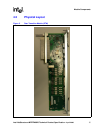
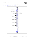
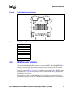
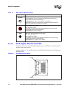
4.3.7 Zone 3 Rear Transition Module Data/Control Connectors
The MPRTM0020 implementation includes three data connectors (P31, P32, P33) that mate
directly to the MPCBL0020 Single Board Computer without connecting through the backplane.
Each Zone 3 data/control connection consists of 120-pin HM-Zd connector with 40 differential
pairs which allows high-speed signals to be passed between the boards.
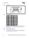
4.3.7.1 Zone 3 Rear Transition Module Data/Control Connector (P31)
The signals that are routed through P31 are the IEEE 1149.1 JTAG signals, SAS storage ports, USB
2.0 signals, and serial and fabric interface Ethernet ports. Table 9 provides the basic pinout of the
connector, and Table 10 provides more detail about the signals.
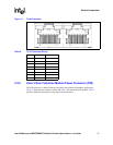
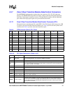
Table 9. RTM Connector (Zone 3) P31 Pinout
PinABCDEFGH
1 RMD_INT# Reserved Reserved TDI Reserved TDO Blue HS LED Reserved
2 SA[1]TX+ SA[1]TX- SA[1]RX+ SA[1]RX- SA[2]TX+ SA[2]TX- SA[2]RX+ SA[2]RX-
3 SA[3]TX+ SA[3]TX- SA[3]RX+ SA[3]RX- No Connect No Connect No Connect No Connect
4 FI_DA1+ FI_DA1- FI_DB1+ FI_DB1- FI_DC1+ FI_DC1- FI_DD1+ FI_DD1+
5 FI_DA2+ FI_DA2- FI_DB2+ FI_DB2- FI_DC2+ FI_DC2- FI_DD2+ FI_DD2+
6 LNK[0]- ACT[0]- SPD1000[0]- LNK[1]- ACT[1]- SPD1000[1]- Reserved Reserved
7 Reserved Reserved Reserved Reserved Reserved Reserved PCIe_CLK+ PCIe_CLK-
8 Reserved Reserved Reserved Reserved Reserved Reserved Reserved Reserved
9 Reserved Reserved Reserved Reserved Reserved Reserved Reserved Reserved
10 USB[0]+ USB[0]- DSR# RXD# RTS# TXD# CTS# DTR#
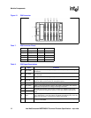
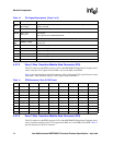
Table 10. P31 Signal Descriptions (Sheet 1 of 2)
Pin Signal Comments
A1 RMD_INT#
This signal is driven by the RMD on non-intelligent RTMs to alert the SBC that there is a
sensor needing attention. It is required on all SBCs and RTMs.
B1, C1 Reserved Reserved
D1 TDI
Test Data In signal as defined in JTAG. SBCs must connect this signal into the test data chain
(i.e., in line with TDO connections from other chips), but must have a means to bypass this
connection if an RTM is not installed.
E1 Reserved Reserved
F1 TDO Test Data Out signal as defined in JTAG. See TDI comments above. Output of RTM
G1 Blue HS LED Blue Hot Swap LED
H1 Reserved Reserved
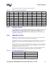
A2-D3
SA[x]TX+, SA[x]TX-,
SA[x]RX+, SA[x]RX-
Storage architecture signals for transmit and receive portions of differential pairs. Three SAS
ports are routed to the RTM.
E3-H3 No Connect No Connect
A4-H5 FI_Dxy+, FI_Dxy-
PHY-level 10/100/1000Base-T signaling routed to the RTM. Row 4 is for the first Ethernet port,
row 5 is for the second Ethernet port. These Ethernet ports are routed from the “Physical
Level” Fabric Interface of the MPCBL0020 Single Board Computer, and have gone through
the magnetics on the SBC.