


Start-up and Calibration 17
3
89VP Instruction Manual Section 3: Start-up and Calibration
PN 51-389VP January 2013
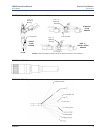
Sensor Preparation
Shake down the sensor to remove any air bubbles that may be present at the tip of the pH glass
bulb. In most cases, the pH sensor can simply be installed as shipped and readings with an accura-
cy of ± 0.2 pH may be obtained. To obtain greater accuracy or to verify proper operation, the sen-
sor must be calibrated as a loop with its compatible analyzer or transmitter.
389VP pH Calibration
1. After a temporary connection is established between the sensor and the instrument, a buffer
calibration may be performed.
2. Consult appropriate pH/ORP analyzer or transmitter instruction manual for specific calibration
and standardization procedures, or see below for recommended two point buffer calibration
procedure.
Recommended two point buffer calibration procedure
Select two stable buffer solutions, preferably pH 4.0 and 10.0 (pH buffers other than pH 4.0 and
pH 10.0 can be used as long as the pH values are at least two pH units apart).
NOTE: A pH 7 buffer solution reads a mV value of approx. zero, and pH buffers read approx. +/-
59.1 mV for each pH unit above or below pH 7. Check the pH buffer manufacturer specifications
for millivolt values at various temperatures since it may affect the actual value of the buffer solu-
tion mV/pH value.
1. Immerse sensor in the first buffer solution. Allow sensor to adjust to the buffer temperature
(to avoid errors due to temperature differences between the buffer solution and sensor tem-
perature) and wait for reading to stabilize. The value of buffer can now be acknowledged by
analyzer/transmitter.
2. Once the first buffer has been acknowledged by the analyzer/transmitter, rinse the buffer solu-
tion off of the sensor with distilled or deionized water.
3. Repeat steps 1 and 2 using the second buffer solution.
4. Once the analyzer/transmitter has acknowledged both buffer solutions, a sensor slope
(mV/pH) is established (the slope value can be found within the analyzer/transmitter).
5. The slope value should read about 59.1 mV/pH for a new sensor and will decrease over time
to approximately 47 - 49 mV/pH. Once the slope reads below the 47-49 mV/pH range, a new
sensor should be installed to maintain accurate readings.
Recommended pH Sensor Standardization
For maximum accuracy, the sensor can be standardized on-line or with a process grab sample after
a buffer calibration has been performed and the sensor has been conditioned to the process.
Standardization accounts for the sensor junction potential and other interferences.
Standardization will not change the sensor’s slope but will simply adjust the analyzers reading to
match that of the known process pH.
1. While obtaining a process solution sample (it is recommended that the sample is taken close
to the sensor), record the pH value that is shown on the analyzer/transmitter display.
3.1
3.2
3.2.1
3.2.2
Section 3: Start-up and Calibration