


!!%"#$
support.dell.com Rack Installation Guide 1-7
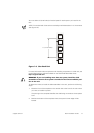
You must allow 3U (5.25 inches) of vertical space for each system you install in the
rack.
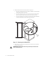
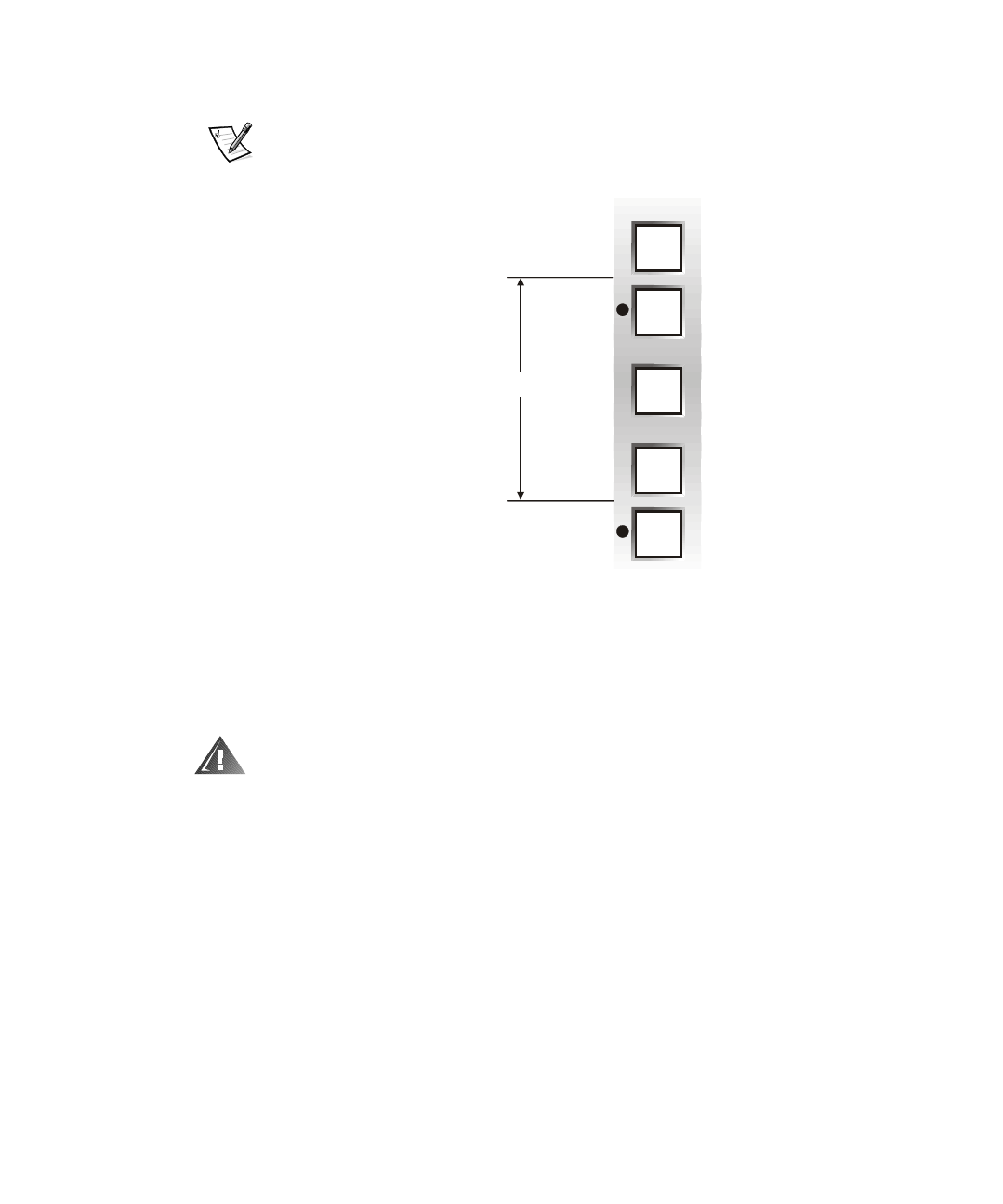
NOTE: The vertical rails of the rack are marked by small indentations in 1-U increments
(see Figure 1-6).
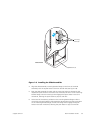
Figure 1-6. One-Rack Unit
For more information about requirements for installing components in a Dell rack, see
the Dell Rack Advisor software available on the Dell World Wide Web site at:
http://support.dell.com
.
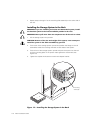
WARNING: If you are installing more than one system, install the slide
assemblies so that the first system is installed in the lowest available posi-
tion in the rack.
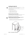
To determine where to install the slide assemblies in the rack, perform the following
steps:
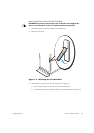
1. Place the front of the template on the vertical rails at the front of the rack where
you want to install the system.
The printing on the template identifies the side facing outwards as the template
front.
2. Position the bottom of the template where the system’s lower edge will be
located.
1 U (1.75 inches)