


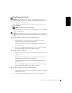

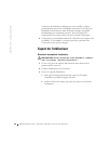

Memory Riser Board Replacement 19
Installing Memory Riser Boards
NOTICE: System board memory sockets 3 and 4 can either be empty or
contain CRIMMs. Sockets 3 and 4 cannot contain RIMMs with memory riser
boards installed in sockets 1 and 2.
1
If any RIMMs occupy memory sockets on the system board, remove
those modules.
NOTE: See "Removing a Memory Module."
To locate the memory sockets on the system board, see "System Board
Memory Components."
NOTICE: To avoid damage to the memory riser board, press the riser board
straight down into the socket with equal force applied at each end of the riser
board.
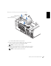
2
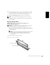
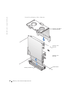
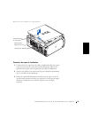
Install memory riser board B (see the following figure):
a Align the slots on the bottom of riser board B with the ridges
inside memory socket 2 on the system board.
The memory sockets on the riser board will face away from the
microprocessor(s).
b Press riser board B straight down into socket 2 until the securing
clips snap into place at the ends of the riser board.
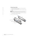
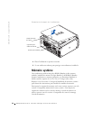
3 Install memory riser board A:
a Align the edges of riser board A with the retention brackets on riser
board B.
b Align the slots on the bottom of riser board A with the ridges
inside memory socket 1 on the system board.
The memory sockets on the riser board will face away from the
microprocessor(s).
c Press riser board A straight down into socket 1 until the securing
clips snap into place at the ends of the riser board.
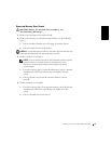
4 Install the memory riser board retention bracket:
a Lower the bracket to the chassis so that the two bracket tabs insert
into the chassis slots.
b Press the bracket straight down until it is secured in the chassis.