


SLR • SLC • SLD OPERATOR INSTALLATION GUIDE
- 9 -
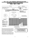
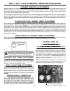
Auto Close Timer Adjustment: This 270-degree adjustable potentiometer will signal the operator to close automatically,
provided no open, reversing or obstruction signals are present from the fully-open position. This timer is adjustable from 0 to 124
seconds. This feature is turned on or off using dip switch #1.
Maximum Run Timer Adjustment: This 270-degree adjustable potentiometer will signal the operator to stop running once it
counts down, unless a limit switch is reached or an input is received first. Each time the motor starts, this timer will begin
counting. This timer is adjustable from 15 to 100 seconds. If the timer expires, the unit locks out and the emergency alarm
sounds.
Open Direction Current Sense Adjustment: This multiturn potentiometer is used to calibrate the built-in current sensing
feature for detection of obstructions while running in the open direction.
Close Direction Current Sense Adjustment: This multiturn potentiometer is used to calibrate the built in current sensing
feature for detection of obstructions while running in the closed direction.
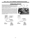
Master/Slave Connection Block: This terminal block is used in conjunction with two operators to configure two gates to open
and close together.
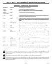
Dip Switches:
#1 This switch turns the auto close timer off/on.
#2 This switch is used in conjunction with alarms and flashing lights that may be added to the operator. When the switch is
in the ON position, these devices will start approximately two seconds prior to the operator starting. In the OFF position,
the devices will only work while the operator is running.
#3 This switch is used in conjunction with single-button controls and radio receivers. In the ON position, successive inputs
will cause signals in the order of OPEN-STOP-CLOSE-STOP. In the OFF position, inputs will cause an OPEN signal
unless the gate is fully open, in which case it will signal CLOSE.
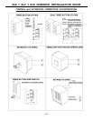
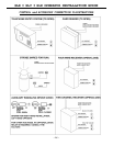
#4 This switch determines right-hand vs. left-hand behavior. When looking from inside the protected area toward the gate, the
side of the drive the operator is on determines its hand of operation. In the OFF position, the operator is set for right-hand.
#5 When turned ON, this switch will allow a one-second delay for solenoid locks to unlock before the motor starts.
#6 In the ON position, the reverse delay is three seconds. In DC operators only, this also disables the inherent DC brake
(provided the R2 brake resistor is cut, see picture above). In the OFF position, the reverse delay is 1 1/2 seconds and the
DC inherent brake is enabled.
#7 Not used at this time.
#8 This switch is used to set Master/Slave configuration. Operators which are stand-alone or master units should be set to
OFF, while only slave units should have this switch set to ON.
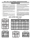
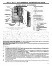
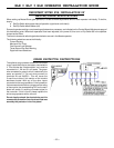
CONTROL BOARD ADJUSTMENTS
NOTE: DO NOT FORCE 270-DEGREE POTENTIOMETERS
BEYOND THEIR NORMAL RANGE OF MOTION
OR DAMAGE MAY RESULT!
Control Board
with DC
Motor Board
DIAGNOSTIC
L.E.D.s
TERMINAL STRIP #2
CONNECTOR
TERMINAL STRIP #1
CONNECTOR
LIMIT SWITCH
CONNECTOR
LIMIT SWITCH
L.E.D.s
3A Fuse
2A Fuse
R2
BRAKE
RESISTOR
3-05-8