


SLR • SLC • SLD OPERATOR INSTALLATION GUIDE
- 10 -
You must follow all required safety precautions and instructions at all times. Review the safety brochure
included with the operator. If any pages are missing or unreadable, contact OSCO at 1-800-333-1717 to request
additional copies.
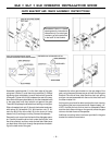
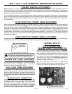
Never connect a button station within reach of the gate or on the side of the gate operator.
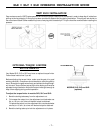
Do not adjust the circuit board current sensing feature too high. It should be adjusted high enough to keep the
gate from falsely triggering the sensing, but no higher than necessary for the gate to operate. Do not defeat the
purpose of this function!
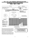
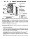
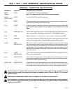
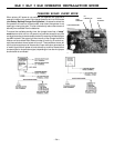
TERMINAL CONNECTION DESCRIPTIONS
TERMINALS FUNCTION DESCRIPTION OF FUNCTION
24VAC 24VAC Provides 24Volt AC power for accessories.
24VAC N Note: DC models will NOT have 24Volt AC power available.
24VDC+ 24VDC Provides 24Volt DC power for accessories.
24VDC- COMM.
1 & 4 OPEN Opens the operator. Several accessories such as button stations, keypads, trans-
mitters and card readers can be wired to open.
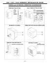
3 & 4 CLOSE Closes the operator. Use caution when wiring accessories to these terminals. The
gate must be clearly visible from the location of any accessories wired to
close.
4 & 5 SINGLE-BUTTON Performs the single-button function which will alternate between open and close or
open, stop and close - depending on dip switch #3. (See page 9 for details.)
2 & 4 STOP Stops the operator. If no stop button is used, a jumper is required across 2&4.
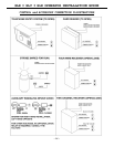
4 & 6 REVERSE This function will cause a reversal when the gate is traveling closed and will travel
back to the fully open position. Loop detectors are often wired for reverse.
4 & 50 OPEN This function works only while the operator is opening. Any signal to this function
will cause the gate to stop, reverse a short distance, and then stop again. At this
time the auto close timer is disabled, and a renewed input will be required to start
the gate again. Should the gate be restarted and the signal occur again prior to
reaching a limit, the gate will stop again, and this time will sound the emergency
alarm and lock out.
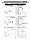
4 & 51 CLOSE This function works exactly like the OPEN OBSTRUCTION, except that it will only
work in the closing direction.
4 & 11 SHADOW/HOLD This function will keep the gate in its fully open position while the signal is present.
This is typically used with a loop and loop detector to keep a large swing gate open
while vehicular traffic is passing through.
24VDC+ & 60 RUN/PRE-START A 24Volt DC device such as a strobe light or alarm can be wired to these terminals.
Depending on dip switch #2, these devices will either begin three seconds before
the operator starts, or only while the motor is running. (See page 9 for details.)
OBSTRUCTION
OBSTRUCTION
3-05-8