


SLR • SLC • SLD OPERATOR INSTALLATION GUIDE
- 13 -
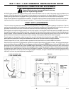
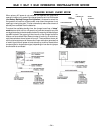
IMPORTANT NOTES FOR INSTALLATION OF
MASTER/SLAVE APPLICATIONS
When setting up Master/Slave gate operators, it is best to make adjustments and run each operator individually. To do this,
simply:
a. Set Dip Switch #4 to proper hand of operation (right-hand or left-hand)
b. Set Dip Switch #8 as Master (off)
Run each operator making current sensing adjustments as necessary, as indicated on the Control Board Adjustments page of
this installation guide. When both operators have been adjusted, turn power off, then turn on Dip Switch #8 in the operator
chosen as the Slave.
The timer to close and radio/single button behavior are set in the Master operator.
The following selections are set individually:
Current Sensing
Maximum Run Timer
One-Second Lock Release
Three-Second Pre-Start Warning
Right/Left-Hand Selections
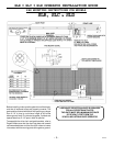
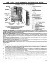
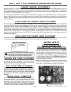
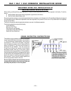
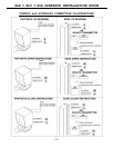
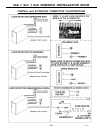
SURGE PROTECTOR INSTRUCTIONS
The optional surge protector should be connected
to any inputs that have an accessory connected to
it. This includes the 3-button station, so it must be
connected to 1, 2A and 3 in all cases. The green
wire connected to ground, which is electrically the
same as terminal 4. The red wires connect to
terminals 2A and 24VDC+. This will cause the
2 amp fuse to blow if this section of the module
becomes shorted. With any of the other inputs
connected to the surge protector, if their protection
line becomes shorted due to a surge over the rating
of the module, the corresponding LED on the main
board will remain lit, causing a constant signal to
the controller. If this is found, please replace the
entire surge protector with a new unit.
Do not simply unhook the shorted wire, as this
removes the protection from the circuit that was
saved by the protector in the first place!