


SLR • SLC • SLD OPERATOR INSTALLATION GUIDE
- 6 -
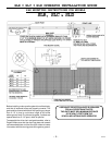
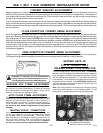
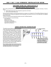
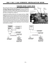
GATE BRACKET AND CHAIN ASSEMBLY INSTRUCTIONS
Assemble a gate bracket (1) to the front edge of the gate,
using two U-bolts (2), and mounting hardware (3). Before
tightening down completely, be sure the bracket is parallel
to the gate. Tighten the U-bolt hardware the rest of the way,
then screw the square head bolts (4) into the threaded holes
in the gate plate until they bottom out against the gate.
These will help keep the bracket from twisting on the pipe.
Slide a threaded chain pin (5) through the bracket as shown,
with spring (6), flat washer (10), and two hex nuts (7). At-
tach one end of the drive chain (8) to the chain pin using
master link (9) and begin unrolling it toward the operator.
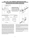
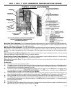
Remove the rain cover from the back of the slide gate opera-
tor. Carefully thread the drive chain under the first idler, over
the drive sprocket, and then under the last idler. Make sure
you feed most of the chain through the sprockets for attach-
ing to the back end of the gate.
Assemble the other gate bracket on the rear edge of the
gate, using the same process as you did with the front gate
bracket. Once this is done, take the other chain pin, spring
and jam nuts and assemble with the end of drive chain and
the other master link.
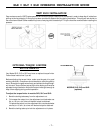
At this point you should be able to adjust the chain tension
by tightening the jam nuts on each end. Approximately 1/4”
to 3/8” of slack per foot of drive chain is acceptable. Make
sure the chain does not drag on the ground, across the gate
rollers or the idler frame of the operator.
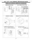
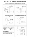
Additional mounting holes have been provided in the gate
bracket for installer convenience.
Numbered items in these
drawings are for instructional
reference only. For actual part
numbers, go to the parts lists
in the back of this booklet.