


SLR • SLC • SLD OPERATOR INSTALLATION GUIDE
- 4 -
10-04-6
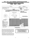
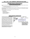
WIRING SPECIFICATIONS
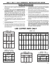
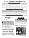
1. Select from the chart at the bottom of this page corre-
sponding to the model, voltage and horsepower rating of
your operator.
2. The distance shown on the chart is measured in feet from
the operator to the power source. DO NOT EXCEED THE
MAXIMUM DISTANCE. These calculations have been
based on standard power supplies with a 10% allowable
voltage drop. If the available voltage is less than the stan-
dard rating, the wire lengths listed may be longer than
what your application will handle. If this is the case, you
should not allow your wire length to reach the upper end
of the chart for the gauge of wire you are using.
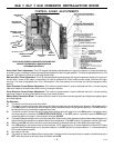
3. When large-gauge wire is used, a separate junction box
(not supplied) may be needed for the operator power con-
nection.
4. All control devices are now 24VDC, which can be wired
considerable distances.
5. Wire length calculations are based on the National Elec-
trical Code, Article 430 and have been carefully deter-
mined based on motor inrush, brake solenoids, and op-
erator requirements.
6. Connect power in accordance with local codes. All power
wiring should be done by a licensed electrician. The green
ground wire must be properly connected.
7. Wire insulation must be suitable to the application.
8. Control wiring must be run in a separate conduit from power
wiring. Running them together may cause interference and
faulty signals in some accessories.
9. Electrical outlets are supplied in all 115VAC models for
convenience with occasional use or low power consump-
tion devices only. If you choose to power dedicated equip-
ment from these devices, it will decrease the distance for
maximum wire length and the charts will no longer be
accurate.
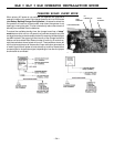
10. A three-wire shielded conductor cable is required to con-
nect master and slave operators. You must use Belden
8760 Twisted Pair Shielded Cable (or equivalent) only –
OSCO part number 2500-1982, per foot). See page 9 for
details of this connection, as well as dip switch selection.
Note: The SHIELD wire should be connected in both
the master and slave operators.
USE COPPER WIRE ONLY!
MODEL SLR SLC
ACCESSORY WIRING
All Models
24VDC
*Over 350 ft. use DC power.
0-2000
14
24VAC
250
350*
14
12
Volts
Maximum
Distance (ft.)
Wire
Gauge
gniriWrewoP
stloV
PH&
ecnatsiDxaM
lauDelgniS
eriW
eguaG
V511
2/1
PH
034
486
0901
2371
6572
512
243
545
668
8731
21
01
8
6
4
MODEL SLD
MODEL SLD
ACCESSORY WIRING
All DC Models
24VDC
*Over 350 ft. use DC power.
0-2000
14
Volts
Maximum
Distance (ft.)
Wire
Gauge
MODEL SLC
MODEL SLR
gniriWrewoP
stloV
PH&
ecnatsiDxaM
lauDelgniS
eriW
eguaG
V511
2/1
PH
613
205
008
2721
2202
851
152
004
636
1101
21
01
8
6
4
stloV
PH&
ecnatsiDxaM
lauDelgniS
eriW
eguaG
V032
2/1
PH
467
8121
6391
6703
6984
283
906
869
8351
8442
21
01
8
6
4
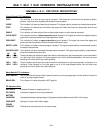
Power Wiring
Volts &
HP
Max Distance
Wire
Gauge
Volts &
HP
Max Distance
Wire
Gauge
Volts &
HP
Max Distance
Wire
Gauge
Single Dual Single Dual Single Dual
115V 222 111 12 208V 760 380 12 230V 894 447 12
354 177 10 1200 600 10 1422 711 10
566 283 8 1924 962 8 2264 1132 8
1/2 900 450 6 1/2 3060 1830 6 1/2 3600 1800 6
HP 1430 715 4 HP 4864 2432 4 HP 5724 2862 4
115V 178 89 12 208V 604 302 12 230V 710 355 12
282 141 10 958 478 10 1128 564 10
450 225 8 1526 763 8 1796 898 8
3/4 716 358 6 3/4 2424 1212 6 3/4 2852 1426 6
HP 1140 570 4 HP 3856 1928 4 HP 4538 2269 4
115V 160 80 12 208V 544 272 12 230V 640 320 12
254 127 10 864 432 10 1016 508 10
406 203 8 1374 686 8 1616 808 8
646 323 6 2184 1092 6 2570 1285 6
1HP 1026 513 4 1HP 3476 1738 4 1HP 4090 2045 4