


28 of 53 Doc 6001242 (01-20273) Rev C
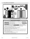
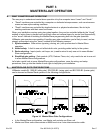
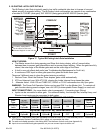
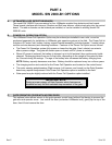
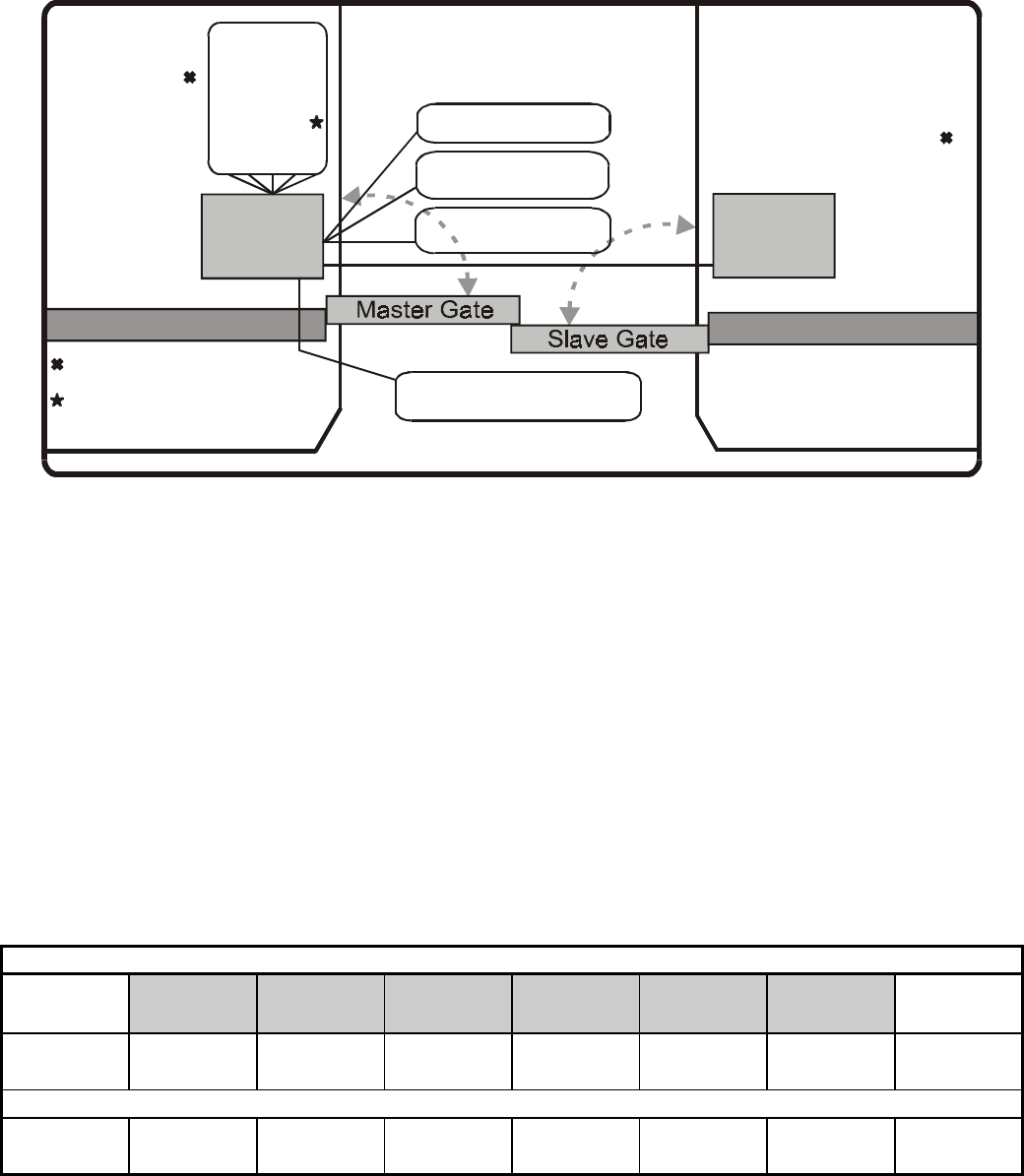
2. BI-PARTING LATCH GATE DETAILS
The Bi-Parting Latch Gate is typically used in low traffic residential sites due to its ease of use and
added security of magnetic locking. The Bi-Parting Latch configuration can consist of any combination
of models SL 1000-B1 (slide gate), SW 2000-B1 (swing gate) and BG 3000-B1 (barrier gate).
STREET
COMPLEX
Gate
Operator
Master
Gate
Operator
Slave
Exit Loop
Inside Interrupt
Loop
Shadow Loop
Outside Interrupt
Loop
Fence
Fence
INPUTS:
Radio
Cycle
Interrupt Bar
Fire
MagLock
Manual
Inputs
SWITCH S1
SETTINGS:
Slide: Unit
Option
Timer: Sys.
Option
Retry: Sys.
Option
ATG: Sys.
Option
Master: ON
Trap: OFF
SWITCH S1
SETTINGS:
Slide: Unit
Option
Timer: OFF
Retry: OFF
ATG: OFF
Master: OFF
Trap: OFF
1204F21
Master/Slave Cable
Connect MagLock to one unit only.
For safety, setting MUST
be the same for both units.
Figure 17. Typical Bi-Parting Latch Gate Installation
HOW IT WORKS:
• The Master moves first during opening and Slave first during closing, with a 2 second delay
between them to prevent gate intercollision and to ensure proper latching. When the gates are fully
closed, the outer edge of the Master gate rests on the outer edge of the Slave.
• A fault in one unit affects both units (see Troubleshooting/Maintenance for Fault List).
• A continuous FIRE input in either gate opens the gates and holds them open.
There are 3 different ways to close the gates (entering or exiting):
1. Reclose Timer: When the Reclose Timer expires, gates close automatically.
2. ATG and Interrupt Loop: With ATG ON, clearing the Inside Interrupt Loop closes the gates.
3. Alternate Action:
With ATG and TIMER OFF, RADIO or CYCLE commands close fully open gates.
WARNING: The Power Fail Operation Option can be used ONLY on the Master Unit. To maintain all
gate functions during power outages, use a full UPS (Uninterruptable Power Supply) on each unit.
INPUT CONNECTIONS: (for more details, refer to paragraph L, Connecting Input Wiring)
• Inputs can be connected to either gate. For enhanced safety, the Interrupt Bar, Interrupt Loop, and
Shadow Loop inputs may be connected to both gates.
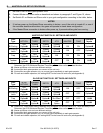
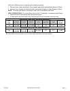
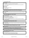
MASTER UNIT SWITCH S1 SETTINGS AND INPUTS
Gate
Type
SLIDE
ACTION
(Reclose)
TIMER
RETRY ATG MASTER TRAP
Operator
Inputs
Bi-Parting
Latch
Unit
Optiono
System
Optionn
System
Optionn
System
Optionn
ON OFF Systemp
SLAVE UNIT SWITCH S1 SETTINGS AND INPUTS
Bi-Parting
Latch
Unit
Optiono
System
Optionn
System
Optionn
System
Optionn
OFF OFF Systemp
n:
Select ATG, Timer and/or Retry from the Master unit and set Slave ATG, Timer and Retry to OFF. Otherwise, the
ATG ON/shorter Reclose Timer/Retry ON in either unit supersedes the other.
o:
For safe and reliable operation, this setting MUST be the same for both units (see Appendix A).
p:
Inputs to one unit affect both gate operators, so you can connect inputs to either unit.