


Rev C Doc 6001242 (01-20273) 25 of 53
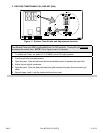
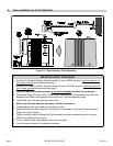
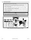
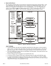
C. MASTER/SLAVE WIRING
Connecting Master and Slave units is fast and easy:
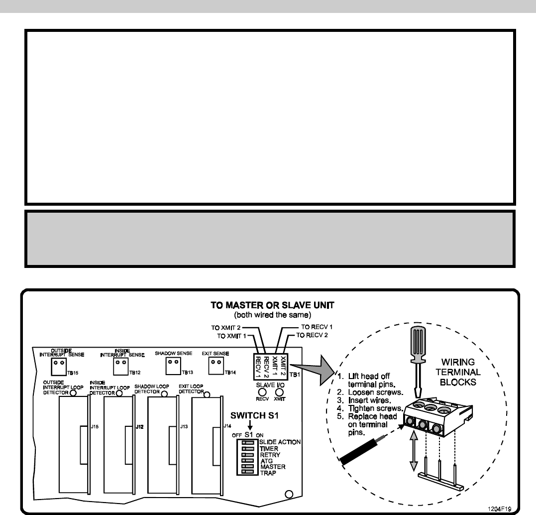
• Master/Slave connections are made through the SLAVE I/O terminal block (TB1), located at
the top right corner of the gate operator controller board (see Figure 15, below).
• Connect the Receive inputs (RECV1, RECV2) on each board to the Transmit inputs (XMIT1,
XMIT2) on the other board.
• To prevent cross-talk between Master/Slave wires and power or input wires, use shielded
cable or run the Master/Slave wires in a separate conduit.
• Use two 18-14 AWG twisted pair wires or a shielded cable containing 2 twisted pair wires for
Master/Slave Interconnection.
• To ensure a reliable communication between Master and Slave units, the maximum allowable
wire length is 3000 feet.
NOTE
Be sure to connect the two units correctly. Improper wiring of the Master/Slave inter-
connection prevents proper operation of the system.
Figure 15. Master/Slave Connection and Switch S1 Location.