


Upright Portable Hot Oil TCUs Chapter 5: Maintenance 34
Pump Assembly
The seal used in this pump is simple to install. If you take care during installation, good
performance will result.
The principle of the mechanical seal is to make contact between the rotary and stationary
members. These parts are lapped to a high finish, and their sealing effectiveness depends on
complete contact. When requesting special seal information, make sure that you give the
pump model number and serial number.
1. Install bracket bushing if required. If bracket bushing has a lubrication groove, install
bushing with groove at 6:00 o’clock position in bracket. If carbon graphite, Refer to
Installation of Carbon Graphite Bushings, page 43.
2. Coat shaft of rotor shaft assembly with non-detergent SAE 30 weight oil. Start end of
shaft in bracket bushing turning from right to left, slowly pushing rotor in casing.
3. Coat idler pin with non-detergent SAE 30 weight oil and place idler and bushing on
idler pin in head. If replacing with carbon graphite bushing, Refer to Installation of
Carbon Graphite Bushings, page 43.
4. Using a .010 to .015 inch head gasket, install head and idler assembly on pump.
Pump head and casing were marked before disassembly to insure proper reassembly.
If not, be sure idler pin, which is offset in pump head, is positioned toward and equal
distance between port connections to allow for proper flow of liquid through pump.
Tighten head capscrews evenly.
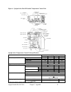
5. Place the mechanical seal installation tapered half rings over the shaft and apply P-80
oil supplied with the replacement seal, grease is not recommended on the sleeve and
rotor shaft. Slide the rotating portion of the mechanical seal on the shaft until it
bottoms on the shaft step. See FIGURE 7 in Appendix. Remove the seal installation
tapered half rings. It is important when using the rings to make sure the thin edge is
facing the direction of the shaft end, and that the thick end is facing the rotor.
6. Apply lubricant to the seal seat o-ring and push it in the bracket. Note the shinny
side of the seat goes towards the carbon graphite seal face.
7. Apply Dow Corning #44 high temperature silicon grease to the lip seal area in the
seal gland and install on the shaft. Install the seal gland plate and secure with two
nuts.
8. Pack ball bearing with Dow Corning #44 high temperature silicon grease and install
in the thrust bearing housing. Place bearing spacer collars inside the lip seals.
Thread the end cap into the bearing housing and tighten with a spanner wrench.
Tighten the radial set screws that lock the end cap in place.
9. Using the snap ring pliers, install the snap ring onto the shaft.
10. Thread the thrust bearing assembly into the bracket. Turn in until hand tight. This
forces the rotor against the head.
11. Put lockwasher and locknut on shaft. Insert length of hardwood or brass through port
opening between rotor teeth to keep shaft from turning. Tighten locknut to 50 – 70
ft.-lbs. torque and bend one tang of lockwasher into slot.
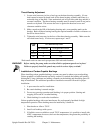
12. Adjust pump end clearance. Refer to section on Thrust Bearing Adjustment.
13. Lubricate all grease fittings with Dow Corning #44 high temperature silicon grease.