


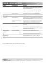

ASSEMBLY AND SET-UP
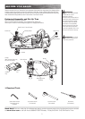
Turn power switch off before conducting any maintenance procedures.
Before you begin, carefully turn unit upside down for easier access.
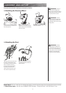
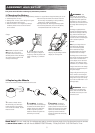
4 Remove both c-clips on the rear
axle between the two bearings.
5 Lightly tap the end of the axle
with a rubber mallet. DO NOT USE
A HAMMER as this will damage
the thread. The brake drum and
sprocket must be slid along the axle
as your tapping progresses.
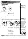
2 Use a 3mm Allen wrench to
loosen the brake.
6 When the axle end is clear of
the bearing hanger, remove the
axle.
3 Use a 3mm Allen wrench to loos-
en the set screw on the sprocket.
q Removing Rear Axle
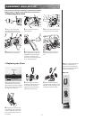
q Replacing the Chain
Master Link
1 Locate the master link on the
replacement chain and with a flat
head screwdriver carefully disengage
the clip from the chain to remove the
link plate and connector link.
2 Wrap the chain around both
sprockets and tension idler. Insert
the connector link all the way
through the chain and fit the link
plate over the connector link.
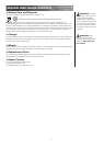
3 Using a flat head screwdriver,
carefully re-attach the clip on to the
link plate. The clip must point in the
drive direction of chain rotation.
Note: Chain should be periodically
checked for grime build-up. If
necessary remove any dirt and/or
debris in and around the chain and
re-lubricate with WD-40.
secure clip
link plate
connector link
Master Link:
1 Using a 17mm open wrench
loosen locknut and remove rear
wheel located closest to the chain.
6
4 If needed, fine-tune the tension
of the chain by using a 19mm open
wrench to adjust the screw on the
motor mounting. Be careful not to
over tighten.
clip
Drive Direction