


38
Appendix
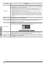
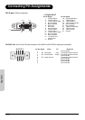
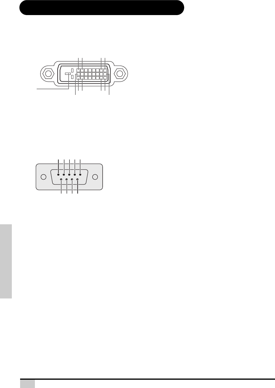
Connecting Pin Assignments
DVI-D port: 25 pin connector
• VI Digital INPUT
RS-232C Port: 9-pin D-sub Female connector of the DIN-D-sub RS-232Cvt cable pin connector
Pin No.Signal Pin No.Signal
1 T.M.D.S data 2- 16 Hot plug detection
2 T.M.D.S data 2+ 17 T.M.D.S data 0–
3 T.M.D.S data 2 shield 18 T.M.D.S data 0+
4 Not connected 19 T.M.D.S data 0 shield
5 Not connected 20 Not connected
6 DDC clock 21 Not connected
7 DDC data 22 T.M.D.S clock shield
8 Not connected 23 T.M.D.S clock+
9 T.M.D.S data 1– 24 T.M.D.S clock–
10 T.M.D.S data 1+ C1 Ground
11 T.M.D.S data 1 shield
12 Not connected
13 Not connected
14 +5V power from
graphic card.
15 Ground
Pin No. Signal Name I/O Reference
1
Not connected
2 SD Send Data Input Connected to internal circuit
3 RD Receive Data Output Connected to internal circuit
4 Not connected
5 SD Signal Ground Connected to internal circuit
6 Not connected
7 Not connected
8 Not connected
9 Not connected
16
8 7
~
2 1
~
~
24
23
18
17
9
C1
4 3 2 1
9
8 7 6
5