


36
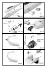
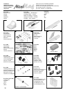
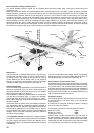
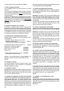
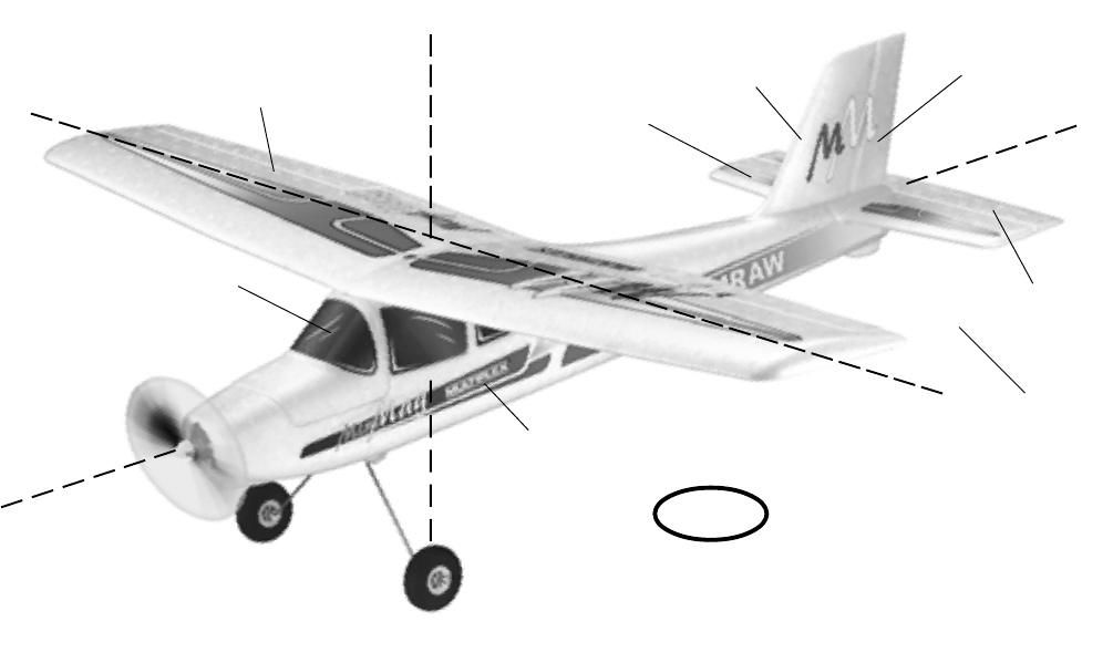
Fuselage
Canopy
L.H. wing
panel
Rudder
Elevator
Fin
Tailplane
R.H. wing
panel
Longitudinal axis
normal axis
lateral axis
GB
Basic information relating to model aircraft
Any aircraft, whether full-size or model, can be controlled around the three primary axes: vertical (yaw), lateral (pitch) and
longitudinal (roll).
When you operate the elevator, the model’s attitude alters around the lateral axis. If you apply a rudder command, the model
swings around the vertical axis. If you move the aileron stick, the model rolls around its longitudinal axis. As our EasyStar has
considerable wing dihedral, ailerons are not required for roll control. In this case the rudder is used both to turn the model
around the vertical axis, and also to roll it (longitudinal axis). External influences such as air turbulence may cause the model to
deviate from its intended flight path, and when this happens the pilot must control the model in such a way that it returns to the
required direction. The basic method of controlling the model’s height (altitude) is to vary motor speed (motor and propeller). The
rotational speed of the motor is usually altered by means of a speed controller. Applying up-elevator also causes the model to
gain height, but at the same time it loses speed, and this can only be continued until the model reaches its minimum airspeed
and stalls. The maximum climb angle varies according to the power available from the motor.
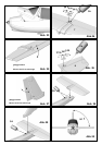
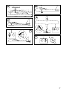
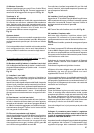
Wing section
The wing features a cambered airfoil section over which the
air flows when the model is flying. In a given period of time the
air flowing over the top surface of the wing has to cover a
greater distance than the air flowing under it. This causes a
reduction in pressure on the top surface, which in turn creates
a lifting force which keeps the aircraft in the air. Fig. A
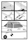
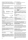
Centre of Gravity (CG)
To achieve stable flying characteristics your model aircraft must
balance at a particular point, just like any other aircraft. It is
absolutely essential to check and set the correct CG position
before flying the model for the first time.
The CG position is stated as a distance which is measured aft
from the wing root leading edge, i.e. close to the fuselage.
Support the model at this point on two fingertips (or - better -
use the MPX CG gauge, # 69 3054); the model should now
hang level. Fig. B
If the model does not balance level, the installed components
(e.g. flight battery) can be re-positioned inside the fuselage. If
this is still not sufficient, attach the appropriate quantity of trim
ballast (lead or plasticene) to the fuselage nose or tail and
secure it carefully. If the model is tail-heavy, fix the ballast at the
fuselage nose; if the model is tail-heavy, attach the ballast at
the tail end of the fuselage.
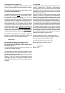
The longitudinal dihedral is the difference in degrees between
the angle of incidence of the wing and of the tail. Provided that
you work carefully and attach the wing and tailplane to the
fuselage without gaps, the longitudinal dihedral will be correct
automatically.
If you are sure that both these settings (CG and longitudinal
dihedral) are correct, you can be confident that there will be no
major problems when you test-fly the model. Fig. C
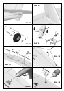
Control surfaces, control surface travels
The model will only fly safely, reliably and accurately if the control
surfaces move freely and smoothly, follow the stick movements
in the correct “sense”, and move to the stated maximum travels.
The travels stated in these instructions have been established
during the test-flying programme, and we strongly recommend
that you keep to them initially. You can always adjust them to
meet your personal preferences later on.
Transmitter controls
The transmitter features two main sticks which the pilot moves
to control the servos in the model, which in turn operate the
control surfaces.
The functions are assigned according to Mode A, although
other stick modes are possible.
The transmitter controls the control surfaces as follows:
Rudder (left / right) Fig. D
Elevator (up / down) Fig. E
Throttle (motor off / on) Fig. F
Unlike the other controls, the throttle stick must not return to
the neutral position automatically. Instead it features a ratchet
so that it stays wherever you put it. Please read the instructions
supplied with your radio control system for the method of setting
up and adjusting the transmitter and receiving system.