


22
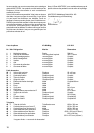
Specification:
Wingspan 1010 mm
Fuselage length overall 820 mm
All-up weight min. 580 g
Wing loading (FAI) min. 26 g/dm²
Power system min. Permax 400 6V
RC functions Elevator, rudder
and throttle; optional ailerons
Important note
This model is not made of styrofoam™! It is
not
possible to glue the material using white glue or
epoxy. Please be sure to use cyano-acrylate glue
exclusively, preferably in conjunction with cyano
activator (“kicker”). For all joints use medium-viscosity
cyano-acrylate (“cyano”). When gluing Elapor®
always use this procedure: spray one surface with
activator, allow it to air-dry, then apply cyano to the
other side. Join the parts and position them accurately
immediately.
Please take care when working with cyano adhesives.
These materials harden in seconds, so do not allow
them to get onto your fingers or other parts of your
body. It is important to wear goggles to protect your
eyes. Keep the adhesive out of the reach of children.
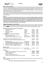
1. Before starting construction
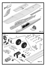
Please check that the contents of your kit are complete.
You will find Figs. 01 + 02 and the Parts List helpful for
this.
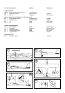
2. Preparing the control snakes
Check the length of the elevator snake tubes 43 and 45
and shorten them if necessary.
43 3 / 2 Ø x 275 mm
45 2 / 1 Ø x 300 mm
Steel 41 0.8 Ø x 355 mm
Repeat the procedure with the rudder snake tubes 44 and
46.
44 3 / 2 Ø x 225 mm
46 2 / 1 Ø x 275 mm
Steel 42 0.8 Ø x 325 mmplease insert!
3. Installing the snakes in the fuselage shells
Caution: it is important to glue the snake outer sleeves 43
and 44 to the fuselage shells over their full length, as this
increases the strength of the tail boom considerably.
Check that the control snakes work smoothly, and be careful
not to allow any glue to run inside the outer sleeves.
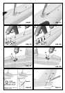
4. Left-hand fuselage shell:
Trim the shell using a balsa knife, as shown in Fig. 03.
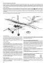
Position the snake outer sleeve 43 in the front of the fuselage
shell, as shown in Fig. 05. Lay the shell down flat, and
glue the outer sleeve 43 to the external channel over its full
length, using cyano.
Installing the servo
Set the servo to neutral (centre) from the transmitter, and
fit the output arm on the output shaft at 90° to the servo
case. Connect the pre-formed end of the steel elevator
pushrod to the second hole from the inside of the servo
output lever. Slip the inner tube 45 over the steel pushrod,
and slide both into the outer sleeve 43 from the servo end.
Fig. 05
Fit the servo in the left-hand fuselage shell from the side as
shown. If you wish to use different servos, it may be
necessary to make minor adjustments here. Tape the servo
lead in the fuselage, so that it does not get in the way
when gluing the fuselage shells together. Glue the servo to
the fuselage with a drop of hot-melt glue at each mounting
lug. Fig. 05
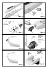
Glue together the wing bolt support components 33 / 34. If
finger power is not sufficient, press them together using
combination pliers, then glue the assembly in the fuselage
shell.
Place the latch clip 22 for the Canopy-Lock canopy retainer
in the fuselage in such a way that the latch lug 23 fits
between the clip 22 and the fuselage side: spray activator
in the recess in the fuselage and allow it to air-dry. Now
apply cyano to the joint surfaces of the latch clip and position
it immediately. Apply more glue to reinforce the joint if
necessary. Fig. 07
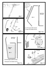
5. Option
If you wish, you can fit a tailwheel to your model. This is
actually necessary if you intend to fit floats at a later date,
as a water rudder is absolutely essential for this version,
and this uses the installed tailwheel wire. Figs. 09 - 13
show the procedure.
You will find a bending template in Figs. 12 + 12a. The
steel wire should be 1.3 mm Ø. The tube required is the
remainder of part 44. Cut the water rudder to shape from 3
mm Depron, and fix it inside the steel wire frame using
adhesive tape. Cut a V-notch in both fuselage shells to
accept the wire, as shown in Fig. 10, and pierce a hole in
the tailplane for it; Fig. 11. If you fit the tailwheel, the integral
foam tailskid on the fuselage should be cut off. Cut a slot
in the rudder for the driver wire; Fig. 10.
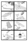
6. Right-hand fuselage shell:
Trim the shell using a balsa knife, as shown in Fig. 04.
Position the snake outer sleeve 44 in the front of the fuselage
shell, as shown in Fig. 06. Lay the shell down flat, and
glue the outer sleeve 44 to the outer channel over its full
length, using cyano.
Installing the servo
Set the servo to neutral (centre) from the transmitter, and
fit the output arm on the output shaft at 90° to the servo
case. Connect the pre-formed end of the steel rudder
pushrod to the innermost hole of the servo output lever.
Slip the inner tube 46 over the steel pushrod, and slide
both into the outer sleeve 44 from the servo end. Fig. 06
Glue the canopy latch clip in place; Fig. 08
7. Joining the fuselage shells
Start with the right-hand fuselage shell 4. We recommend
medium or thick cyano for this stage.
The fuselage shells 3 and 4 can now be glued together.