


24
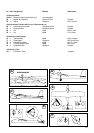
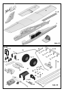
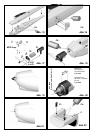
18. Installing the undercarriage
Fit the wheels 71 on the main undercarriage unit 70, using
two collets 72 to retain each one. Fig. 33. Squeeze the
undercarriage together gently, push it into the support 74
and allow it to snap into place. Fig. 34
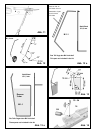
Completing the wings
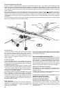
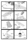
19. Installing the spar
Fit the spar tubes 40 in the spar joiner 31, secure them
with glue and trial-fit them in the wing. Apply cyano to the
spar channel in the wing, then push the spars and the spar
joiner quickly into place. Set the wing straight before the
adhesive has a chance to cure. Sight along the wings from
each tip to check for unwanted warps.
Fig. 35
Optional ailerons
If you wish to fly the model in rudder / elevator form, simply
skip points 19 - 22. The servo wells can be sealed (later)
using the decals provided.
With the standard dihedral the model flies very well with
rudder or ailerons as the primary turning control. It is also
possible to fit ailerons to the wing at any time.
If you wish to fly the model with ailerons (“full-house” control),
resume construction at this point:
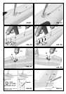
20. Freeing the ailerons, installing the aileron servos
Cut a slot at both ends of the ailerons, which are attached
to the wing 6. Work the ailerons to and fro repeatedly to
free up the hinges; they will eventually move relatively easily.
Take care not to separate the control surfaces!
Fig. 36
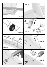
21. Installing the aileron servos
Set the servos to neutral from the transmitter. Fit the output
arms on the servos so that the arms are at 90° to the servo
case - 1 x left, 1 x right.
Check that the servos fit snugly in the recesses in the
wings 6. You may need to make minor adjustments to suit
the servo type you are using. Apply a drop of hot-melt glue
to the slots in the wing for the servo mountings lugs, and
press the servos into the recess immediately. Apply another
drop of glue if necessary.
Fig. 37
22. Deploying the aileron servo leads
Deploy the servo leads along the wing towards the centre
section. The lead must fit in the front edge of the spar
channel and run perfectly straight, standing “on edge”. The
leads should project by about 120 mm at the wing root, so
that you can comfortably connect the plugs to the receiver
when the model is assembled. You may need to extend
the standard servo leads. Secure the leads at the centre of
the wings with a drop of hot-melt glue.
23. Attaching the aileron horns
Fit the pushrod connectors 25 in the outermost hole of the
aileron horns 24. Secure the connectors using the washers
26 and nuts 27. Caution: make a handed pair: 1 x left, 1 x
right. Tighten the nuts gently until the connectors swivel
smoothly, but without slop, then apply a tiny drop of cyano
to the outside of the nuts on the point of a pin. Fit the
socket-head grubscrews 28 in the pushrod connectors 25
using the allen key 29; do not tighten them at this point.
Apply activator to the recesses in the ailerons and glue the
horns 24 in them with the row of holes facing the hinge line.
Fig. 38
24. Installing the aileron pushrods
Connect the pre-formed end of the steel pushrods 30 to the
innermost hole of the servo output arm, and fit the plain
end through the pushrod connector 25 on the aileron horn.
Set the aileron and servo to neutral (centre), and tighten
the grubscrew 28 to secure the pushrod.
Fig. 39
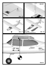
25. Attach the wing to the fuselage using the screw 32.
Fig. 40
26. Installing the radio control system components
The next step is to install the remaining radio components
and the flight battery in the cabin area. Keep one eye on
the recommended Centre of Gravity position when
positioning these items; see Fig. 43.
You can correct the CG position by adjusting the location
of the flight battery.
Pieces of Velcro tape 20 + 21 are supplied in the kit for
securing these components. Please note that the adhesive
on the tape is not very strong, and we recommend that you
stick the tape in the fuselage with cyano for additional
security.
Fit the receiver behind the wing screw, standing upright.
Run the aerial wire out of the fuselage and tape it in place.
The speed controller should be positioned immediately aft
of the motor.
The motor supplied in the kit features internal suppressors,
and these are adequate if you are using a MULTIcont X-16
speed controller, # 7 2271.
If you prefer to use a different controller, it is in your own
interests to fit additional suppression measures to the
electric motor. A suitable suppressor set is available under
# 8 5020. Solder one 47 nF capacitor between one motor
terminal and the motor can, and a second one between the
other terminal and the can. The third 47 nF capacitor should
be soldered across the terminals to form a bridge.
Installing the propeller
The next step is the initial test-run of the motor, but first the
propeller must be fitted. The procedure for this varies
according to the power system you have installed. However,
please be sure it is firmly located in every case. In the
standard version the spinner and propeller should be
secured with a drop of adhesive and glued to the motor
shaft. Use 5-minute epoxy with a Guenter propeller, and
cyano with an MPX prop.
Once the wiring is complete, you are ready to carry out the
first test-run.