


23
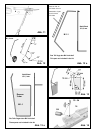
Check that the parts fit together snugly, and carry out any
minor trimming required before reaching for the glue bottle.
Glue the wing bolt support assembly 33 / 34 in one fuselage
shell. Apply a thin coating of activator to the fuselage shell
4 and allow it to air-dry, then apply thick cyano to the mating
surfaces of the fuselage shell 3. Now join parts 3 and 4
carefully and align them quickly. The fuselage joint line must
be straight, i.e. it must not be curved!
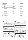
Figs. 14 - 15
8. Installing the undercarriage support
Fit the undercarriage support 74 on the underside of the
fuselage “dry” (no glue), and press the spikes into the
fuselage material. Remove the support, then carefully apply
cyano to the joint surface on the fuselage, not forgetting
the pierced holes. Apply activator thinly to the undercarriage
support, and press it firmly into place. Fig. 16
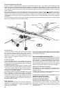
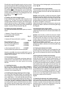
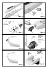
9. Preparing the motor installation
You now have to decide which power system you want to
install:
1. Standard - Permax 400, direct drive
5 x 4” Guenter or MPX propeller
Included in the kit Fig. 17
2. Standard G Permax 400 with 3:1 gearbox
Fig. 20
Easy Glider E power set
(Permax 400 with 3:1 gearbox) # 33 2688
plus 3.5 mm Ø propeller driver # 33 2310
and 8 x 3.8” propeller # 73 3139
3. “Sport” power set: BL-X 22-18 # 33 2627
The set includes the propeller driver and propeller
Attach the motor 50 to the motor mount 60 + 61. If you are
using the geared motor, cut down the motor mount 61 to a
length of 25 mm. Fig. 20
10. Connecting the motor
Carry out a test-run! The propeller must always rotate anti-
clockwise when viewed from the front. Reverse the motor
terminal connections if the motor spins in the wrong
direction.
11. Installing the motor
Dry-fit the motor assembly (no glue): Figs. 19 and 21;
carry out any minor adjustments required. Apply CA to the
whole surface of the motor mount and carefully fit the
assembly in the fuselage. Fig. 18
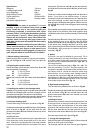
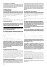
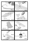
12. Installing the canopy latch lugs in the canopy
The canopy latch lugs 23 are fitted in the canopy 5 as a
mirror-image pair, i.e. with the lugs facing inward. Apply CA
to the ridged areas - in this case activator should not be
used - then push the lugs into the slots in the canopy. Fit
the canopy on the model, and allow the latch lugs to engage
in the latch clips 22. Immediately position the canopy
accurately. Allow the glue to harden for about one minute,
then carefully open the canopy again. Apply activator to
the joint areas between the latch lugs and the canopy.
Fig. 22
Fit the canopy on the fuselage again, and check that it fits
neatly. Fig. 23
13. Attaching the horn to the elevator
Fit the pushrod connector 25 in the outermost hole of the
elevator horn 24, and secure it with the washer 26 and nut
27. Fig. 24
Caution: note the side on which the connector is fitted!
Tighten the nut gently until the connector swivels smoothly,
but without slop, then apply a tiny drop of cyano to the
outside of the nut on the point of a pin. Fit the socket-head
grubscrew 28 in the pushrod connector 25 using the allen
key 29; do not tighten it at this point.
Apply activator to the recess in the elevator, and glue the
prepared horn 24 in it, with the row of holes facing the hinge
line. Fig. 26
14. Attaching the horn to the rudder
Fit the pushrod connector 25 in the outermost hole of the
rudder horn 24, and secure it with the washer 26 and nut
27. Fig. 26
Caution: note the side on which the connector is fitted!
Tighten the nut gently until the connector swivels smoothly,
but without slop, then apply a tiny drop of cyano to the
outside of the nut on the point of a pin. Fit the socket-head
grubscrew 28 in the pushrod connector 25 using the allen
key
29; do not tighten it at this point.
Apply activator to the recess in the rudder, and glue the
prepared horn 24 in it, with the row of holes facing the hinge
line. Fig. 26
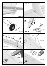
15. Freeing the elevator and rudder
Work the rudder and elevator to and fro repeatedly to free
up the hinges; they will eventually move relatively easily.
Take care not to separate the control surfaces! Figs. 25 +
27
16. Gluing the tail surfaces to the fuselage
Position the tailplane 7 on the fuselage “dry” (no glue) and
check that it fits correctly. Ensure in particular that it is
parallel to the wing saddle, and that there is no gap between
the tailplane and its mount. You can check this by laying
one of the spar tubes 40 on the wing saddle (e.g. secure it
with masking tape). Now sight over the spar from the
fuselage nose and check that the tailplane is parallel to it.
When you are confident that the tailplane can be aligned
correctly, glue it to the fuselage. Check that alignment is
correct and there are no gaps, then leave the glue to cure.
Place the fin 8 on the fuselage and tailplane “dry”, and
check it for fit. It is important here that the fin is a snug fit,
and is at 90° to the wing saddle and the tailplane; use a
setsquare or similar tool to check this.
Fig. 30
17. Retaining the elevator and rudder pushrods
Fit the front end of the steel pushrods 41 and 42 through
the pushrod connectors 25, set the servos and control
surfaces to neutral (centre) and tighten the socket-head
grubscrews 28. You may find it necessary to bend the
pushrods slightly to obtain correct alignment.
Figs. 31 - 32