


12 GTO 4000XLS Instruction Manual © 01.10.12
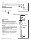
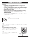
Step 1
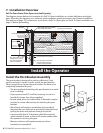
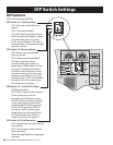
Loosen sealing nut on strain relief hub at bottom of control
box. Insert power cable into control box through strain
relief. Thread approximately 6” of the power cable into the
control box and retighten sealing nut until the power cable
locks into place.
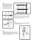
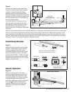
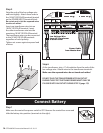
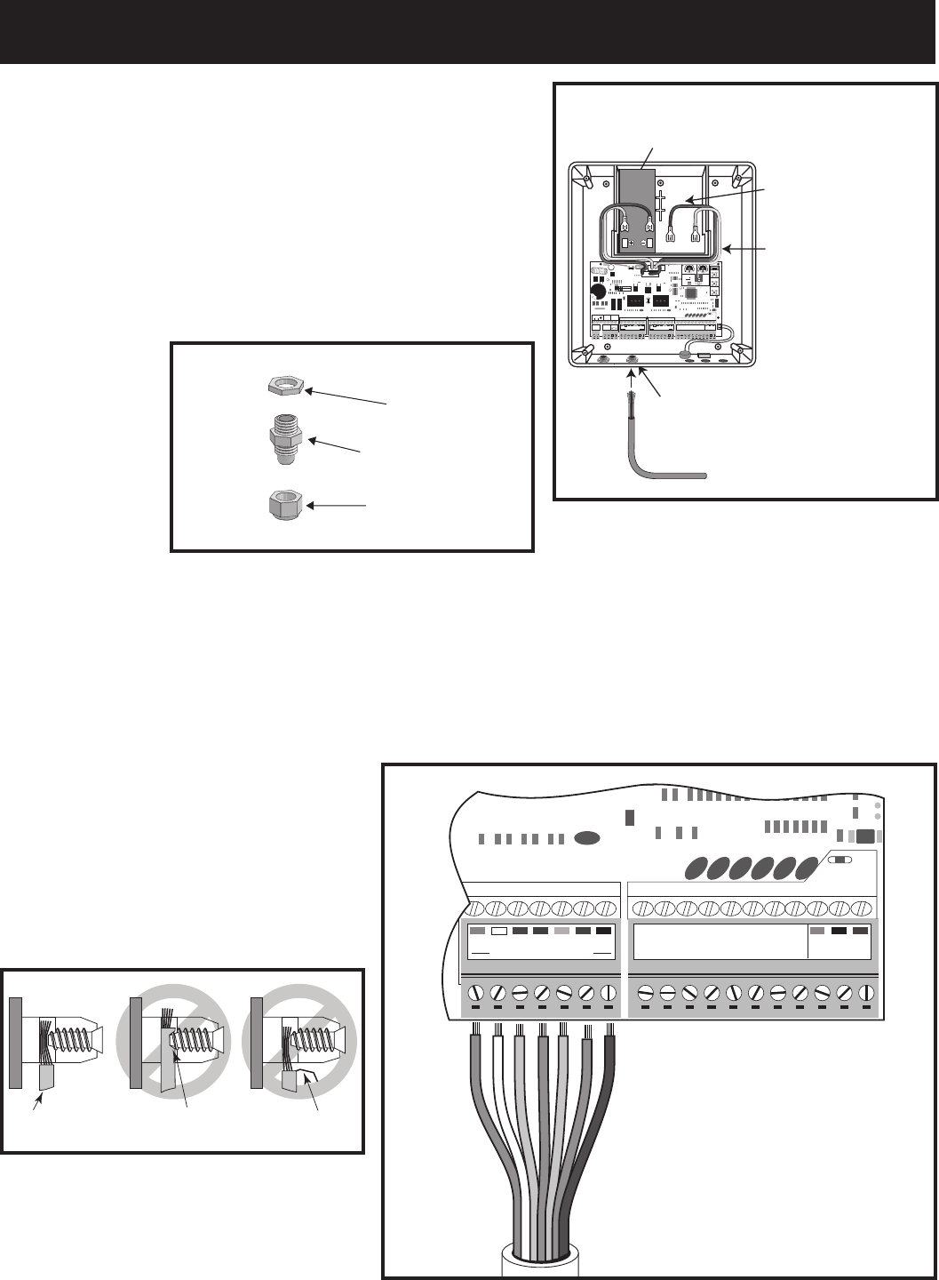
Step 2
Insert the stripped power cable wires into the appropriate terminals on the MASTER OPERATOR terminal
block. Insert the green wire into the GRN terminal, white wire into WHT, blue wire into BLUE, brown wire
into BRN, orange wire into ORG, red wire into RED, black wire into the BLK.
Tighten the set screws against the end of the wires.
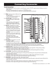
NEVER SPLICE WIRES.
Splicing permits corrosion and
seriously degrades the wire’s ability
to carry an adequate current.
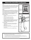
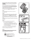
Connect Operator Power Cable
Sealing Nut
Hub
Lock Nut
Strain Relief
Operator Power Cable
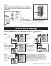
Strain Relief
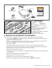
Space for optional
second 12 Volt battery
(see Accessory Catalog)
Space for 12 Volt
battery (included).
GRNCOMCOM
CYCLE
CLOSE
SAFETY
SHADOW
LOOP
CLOSE
EDGE
OPEN
EDGE
EXIT
OPEN
BLK
RECEIVER
RED
25
FUSE
BATT +
BATT -
1 2 3 4
ON DIP
STATUS
LEARN RMT
RECEIVER
LEARN
MAST LIMIT
LEARN
SLV LIMIT
S3
S4
ALM
S2
OFF
SOFT START OFF
WARNING OFF
OPEN PULL
SLV OPEN DLY.
MODE1 OFF
MODE2 OFF
ON
ON
PUSH
SIMULT.
ON
ON
120MIN MAX
CHARGING
PWR IN
ORGBLUEWHTGRN BRN RED
MASTER INPUTS
BLK
SOLAR
or
18 VAC
ORGBLUEWHTGRN BRN RED
SLAVE INPUTS
BLK
LOCK
GTO AUX
GTO
TRANSF
LOCK
PWR
AUX
RLY
POWER
INPUTS
CONTROL
OUTPUTS
MASTER CABLESLAVE CABLE
CONTROL INPUTS
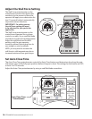
AUTO CLOSE TIME STALL FORCE
Battery wires for
optional second battery.
Power Cable from
the Master Arm
GRNCOM COM
CYCLE
CLOSE
SAFETY
SHADOW
LOOP
CLOSE
EDGE
OPEN
EDGE
EXIT
OPEN
BLK
RECEIVER
RED
RECEIVER
ORGBLUEWHTGRN BRN RED BLK
MASTER OPERATOR
MASTER OPERATOR
CONTROL INPUTS
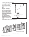
Correct
Wrong Wrong
Wire
Screwed into
wire insulation
Exposed strands
of wire