


GTO 4000XLS Instruction Manual © 01.10.12 9
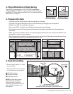
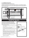
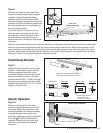
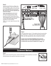
Gate in the
CLOSED POSITION
Pinch Area
2" minimum
MAX 22"
Clamp
Level Operator
Fence Post
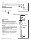
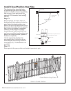
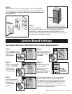
Clevis Pin, Bushing, and Hairpin Clip
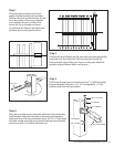
Gate In Open Position
LEVEL horizontal cross member
Mark cross member through middle of
gate bracket slots and drill 1/2" holes
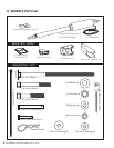
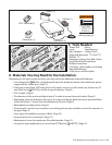
Round Tube & Chain Link Gate
Square Tube Gate
Mounting Plate Created
for Decorative Gate
(required but not supplied)
FRONT VIEW
SIDE VIEW
FRONT VIEW
SIDE VIEW
Step 8
Remove the clevis pin from the front
mount and while supporting the gate
operator, swing the gate and gate
operator to the closed position. With
the gate and gate operator in the closed
position check the clearance and be sure
that the gate operator is not binding at
the post pivot bracket.
Ifyoudon’thave2”clearanceorthe
gate operator is binding on the post
pivot bracket, remove the bolt in the
post bracket and readjust the pivot
bracket until you can achieve the proper
clearance.
With the post pivot bracket in the optimum position for clearance and freedom of movement, replace the
bolt in a post bracket adjustment hole and secure with washer and lock nut. Return the operator to the
open position and reattach the gate bracket. Recheck the gate operator level and clearance in the open
position. Adjustment of the gate bracket will be necessary if the post bracket was moved. After verifying
clearance, make sure the gate bracket is clamped securely.
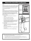
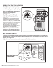
Install Gate Bracket
Step 9
Detach the front mount from the gate
bracket. Check that the gate bracket
holes are centered over the scribe
line. Mark the gate in the center of the
gate bracket holes. Remove the gate
bracket and drill the
1
/2” holes through
the gate cross member and attach the
gate bracket using the
1
/2” x 2
3
/4” bolts,
washers and lock nuts.
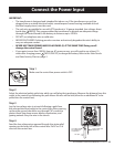
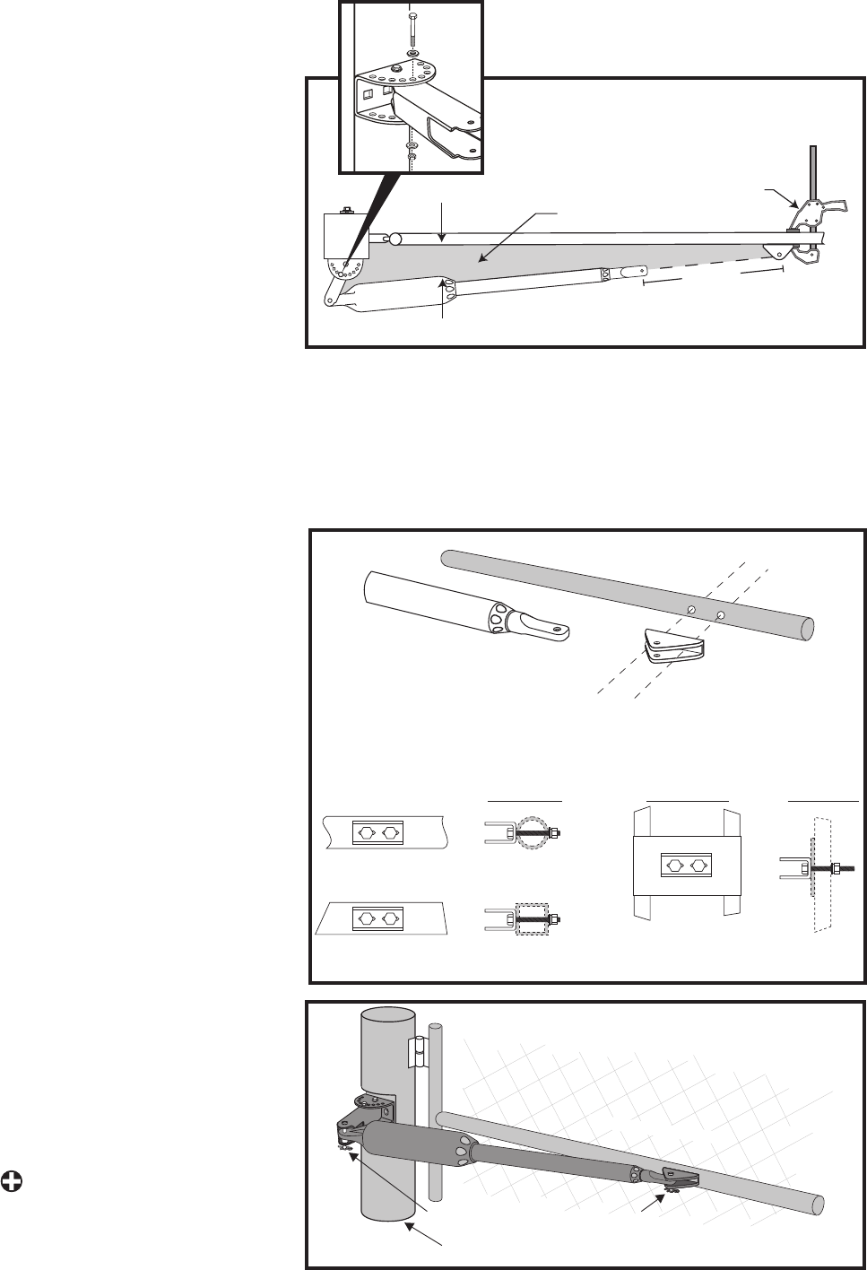
Attach Operator
Step 10
Make sure the gate is in the open
position and the operator arm is fully
retracted. Attach the operator to the
securely bolted post bracket assembly
and gate bracket using clevis pins,
bushings, and hairpin clips, or optional
Pin Lock
[FM345]
. Verify that the
operator is level, bolts are tight, and
adjust the post bracket assembly if
necessary.