


Technical Guide
DAN-LIQ-Turbine Meter-TG-0807
August 2007
Page 4
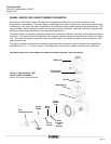
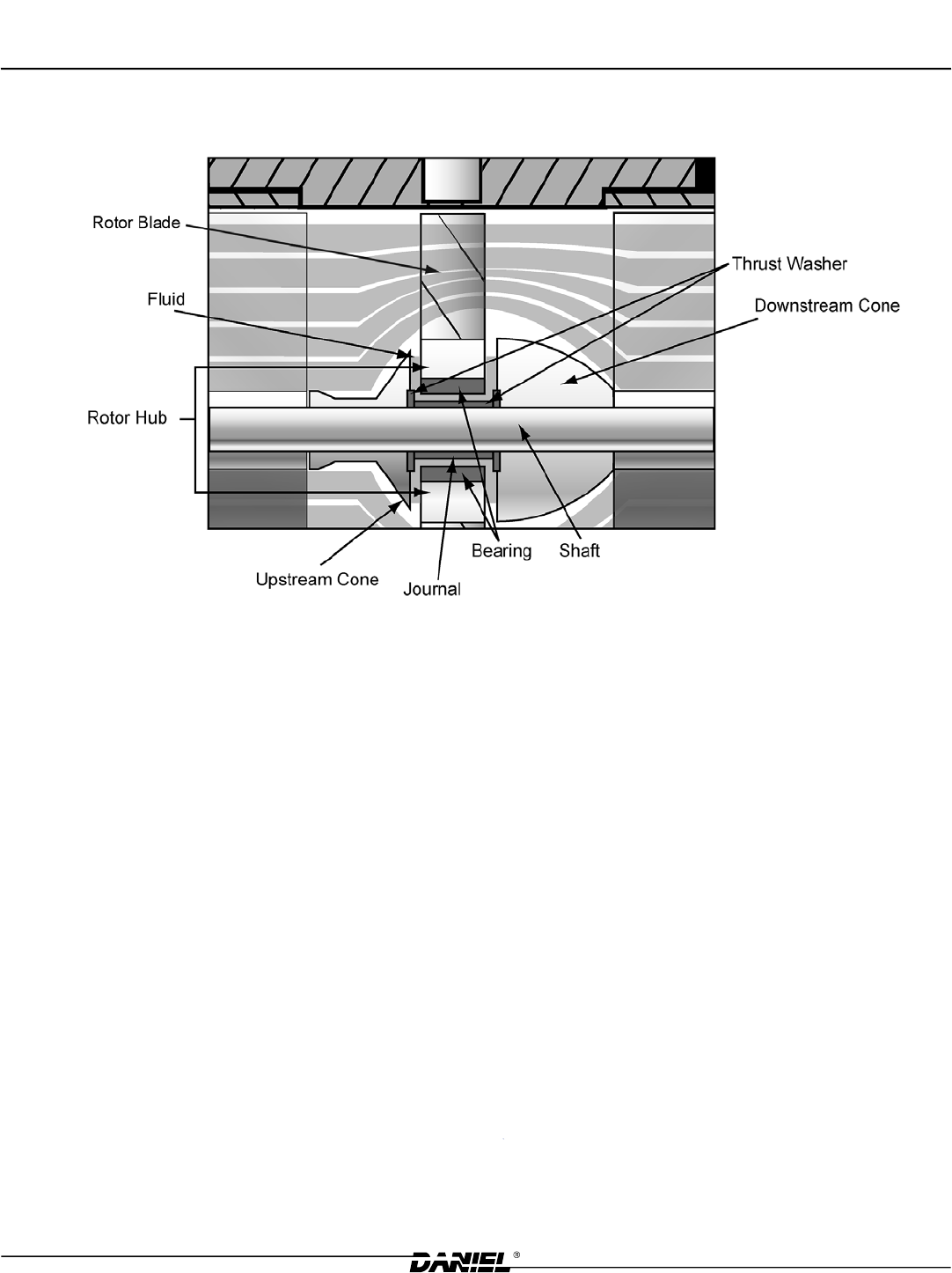
PATENTED* FLOATING ROTOR
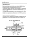
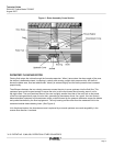
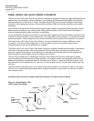
Flowing uid enters the turbine through the forward suspension. When it encounters the sharp angle of the cone,
the stream is deected outward, increasing in velocity and causing a slight static pressure drop. As the uid
leaves the blade area, ow has redistributed. Velocity is reduced slightly and the static pressure has increased
proportionally.
The difference between the two velocity pressures causes the rotor to move upstream into the uid ow. This
upstream force would be great enough to cause the rotor to strike the forward thrust bearing, were it not for
the slight offset. The cross sectional area of the cone is slightly smaller than that of the rotor hub so that some
of the ow impinges directly upon the rotor hub, generating a downstream thrust. As a result, the rotor oats in
balance between upstream and downstream cones, pushed forward by the pressure difference across the blades
and pushed backward by the ow impingement. The only bearing surface other than the measured uid is the
cemented carbide sleeve bearing insert. (See Figure 4)
In bi-directional meters, the downstream cone is replaced by a second upstream cone and rangeability in the
reverse ow direction is reduced.
* U.S. PATENT NO. 3,948,099, PATENTS IN OTHER COUNTRIES
Figure 4 - Rotor Assembly Cross Section