


Technical Guide
DAN-LIQ-Turbine Meter-TG-0807
August 2007
Page 3
Daniel
®
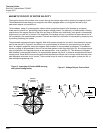
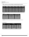
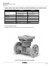
Valves In Load Rack Duty
TURBINE METER THEORY
The basic theory behind Daniel’s electronic liquid turbine meters is relatively simple. Fluid ow through the meter
impinges upon the turbine blades which are free to rotate about an axis along the center line of the turbine
housing. The angular (rotational) velocity of the turbine rotor is directly proportional to the uid velocity through
the turbine. These features make the turbine meter an ideal device for measuring ow rate.
The output of the meter is taken by an electrical pickoff(s) mounted on the meter body. The output frequency of
this electrical pickoff is proportional to the ow rate. In addition to its excellent rangeability, a major advantage
of the turbine meter is that each electrical pulse is also proportional to a small incremental volume of ow. This
incremental output is digital in form, and as such, can be totalized with a maximum error of one pulse regardless
of the volume measured.
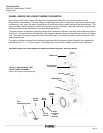
The turbine meter and associated digital electronics form the basis of any liquid metering system. An expanding
blade hanger assembly holds the turbine rotor in alignment with the uid ow. The angle of the turbine blades to
the stream governs the angular velocity and the output frequency of the meter. A sharper blade angle provides a
higher frequency output. In general, the blade angle is held between 20º and 40º to the ow. Lower angles cause
too low of an angular velocity and loss of repeatability, while larger angles cause excessive end thrust.
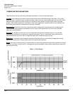
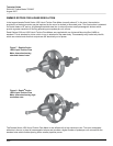
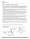
FLOW RATE IS PROPORTIONAL TO ANGULAR VELOCITY
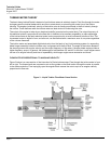
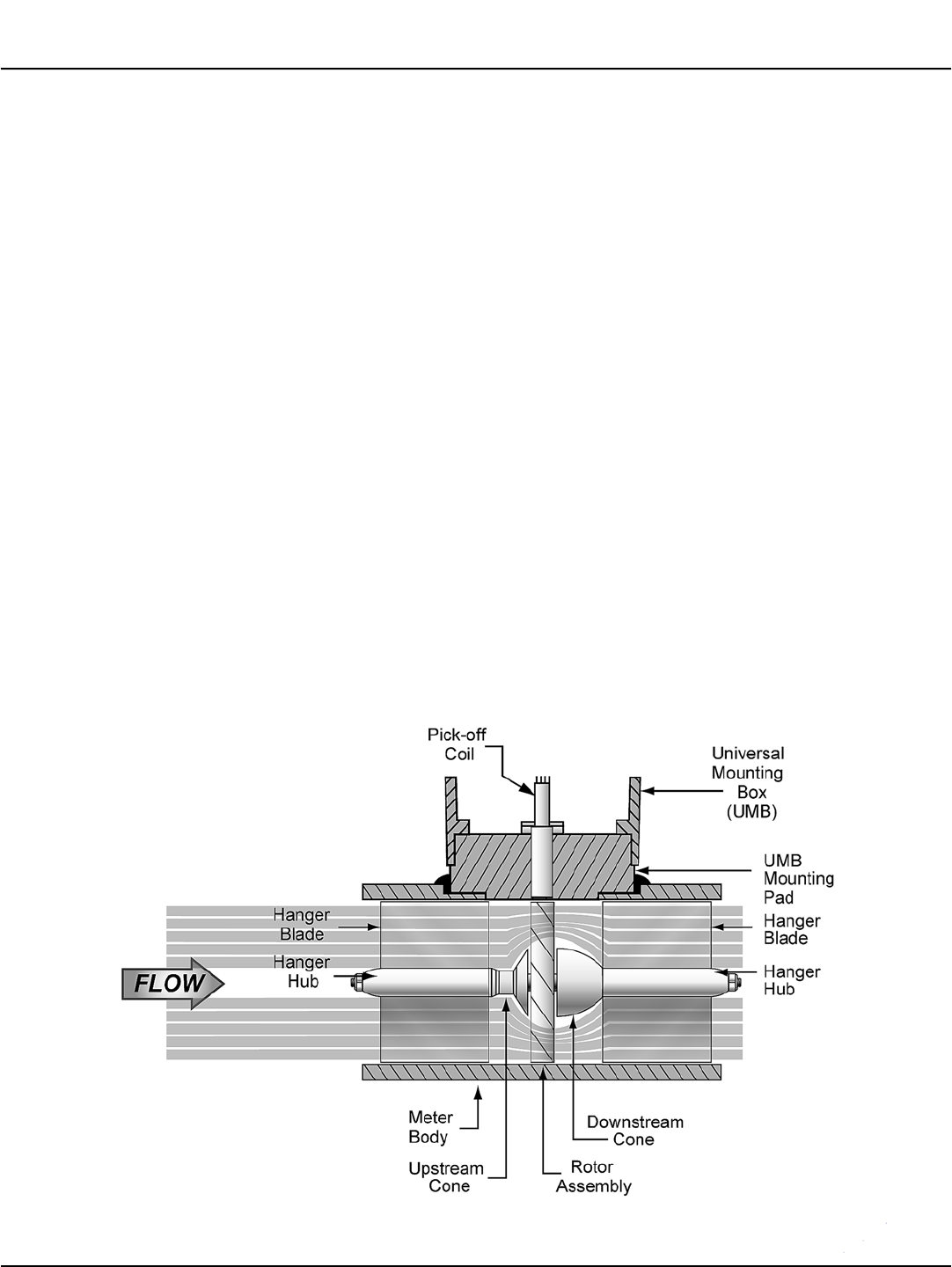
Figure 3 below is a cross section of the internals of a Daniel turbine meter. Flow through the turbine meter is from
left to right. The forward and rear suspension act as ow guides so that uid motion through the meter is parallel
to the meter centerline. Flow impinging upon the angular blade causes the rotor to spin at an angular velocity
proportional to ow rate.
Figure 3 - Liquid Turbine Flow Meter Cross Section