Installing a Filer System 2-13
3. Route the cable through the cable management loop and then to the FC-AL
adapter card in slot 7.
4. Connect the free end of the FC-AL filer-to-PowerVault 700N storage system cable
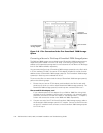
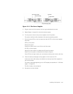
to the filer’s FC-AL adapter card connector in slot 7 (see Figure 2-9). Tighten the
locking screws on the cable’s DB-9 connector.
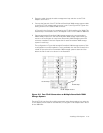
In Figure 2-9, the first loop is connected to the FC-AL0 interface of an 760N. The
second loop is connected to the FC-AL adapter in slot 7 on the 740N or 760N filer.
5. Connect successive PowerVault 700N storage systems by connecting short
DB9-to-DB9 jumpers from the first PowerVault 700N storage system EXP con-
nector to the next-higher (or next lower) PowerVault 700N storage system PRI
connector installed in the rack. Repeat this for each PowerVault 700N storage
system in each loop.
The configuration in Figure 2-9 has eight PowerVault 700N storage systems. Such
a configuration must be installed in a rack, preferably with the filer located in the
middle of the rack and four PowerVault 700N storage systems above and four
below the filer. A rack is not shown in the illustration.
;$&':($2.//
1-
The third FC-AL loop (loop 2) would be connected using this procedure, but using the
FC-AL adapter card in slot 6 for the 740N filer, or using the FC-AL adapter card in slot 4
for the 760N filer.
FC-AL adapter in slot 7
FC-AL0 loop
FC-AL1 loop


